


5
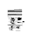
Terminal Connection Diagram
1
INSTALLATION AND WIRING
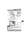
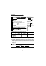
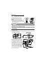
1.4 Terminal Connection Diagram
! Three-phase 200V power input
REMARKS
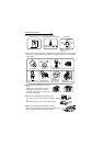
*1. You can change the control logic between sink and source logic. Refer to page 12 for details.
*2. The terminal functions change with input terminal function selection (Pr. 60 to Pr. 63, Pr.
65, Pr. 505). (Refer to page 68)
(RES, RL, RM, RH, MRS, OH, STR, STF, SQ signal, without function selection)
*3. The terminal functions change with output terminal function selection (Pr. 64, Pr. 506).
(Refer to page 69.) (RUN, OL, ALM signal, without function selection)
*4. Only either the personal computer (e.g. GX Developer) or parameter unit can be
connected to the PU connector.
*5. For details of the I/O device, refer to page 109.
CAUTION
To prevent a malfunction due to noise, keep the signal cables more than 10cm away
from the power cables.
Be careful not to short
PC-SD.
NFB
R
S
T
PC
STF
STR
RM
RUN
SE
IM
U
V
W
P1
P
N
MC
SINK
SOURCE
: Main circuit terminal
: Control circuit terminal
SD
*1
RL
RH
DA
DB
DG
SLD
DA
DB
DG
SLD
SLD
FG
Parameter unit
(FR-PU04)
*4
ALM
SQ
Three-phase AC
power supply
External transistor common
24VDC power supply
Contact input common (source)
Forward rotation start
Reverse rotation start
Multi-speed
selection
High
Middle
Low
Sequence start
Contact input common
Control input signals
(No voltage input allowed)
Personal
computer
RS-232C
-RS-485
converter
CC-Link communication signals
PLC CC-Link
master module
Inverter
PU connector
(RS-485)
Motor
Earth
(Ground)
Power factor improving
DC reactor
(FR-BEL: Option)
Jumper: Remove
this jumper when
FR-BEL is connected.
Running
Alarm
output
Output
terminals *3
Open
collector
output
Open
collector
output common
Earth (Ground)
*2
Input terminals
*5
(X0)
(X1)
(X4)
(X3)
(X2)
(X5)
(Y0)
(Y1)
*5