


23
Peripheral Devices
1
INSTALLATION AND WIRING
! Countermeasures
• If the carrier frequency setting is high, decrease the carrier frequency (Pr. 72) of
the inverter.
Note that motor noise increases.
• Using earth leakage circuit breakers designed for harmonic and surge suppression
in the inverter's own line and other line, operation can be performed with the
carrier frequency kept high (with low noise).
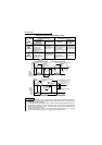
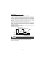
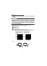
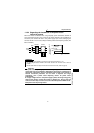
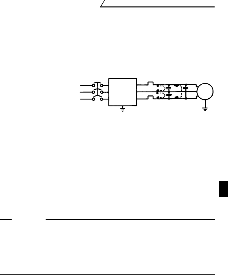
(2) Line-to-line leakage currents
! Countermeasures
• Use the electronic overcurrent protection of the inverter.
• Decrease the carrier frequency. Note that motor noise increases.
To ensure that the motor is protected against line-to-line leakage currents, it is
recommended to use a temperature sensor to directly detect motor temperature.
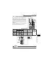
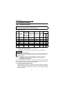
! Installation and selection of no-fuse breaker
On the power receiving side, install a no-fuse breaker (NFB) to protect the primary
wiring of the inverter. Which NFB to choose depends on the power supply side
power factor (which changes with the power supply voltage, output frequency and
load) of the inverter. Especially as the completely electromagnetic type NFB
changes in operational characteristic with harmonic currents, you need to choose
the one of a little larger capacity. (Check the data of the corresponding breaker.) For
the earth leakage circuit breaker, use our product designed for harmonic and surge
suppression. (Refer to page 25 for the recommended models.)
Harmonics of leakage
currents flowing in
static capacities
between the inverter
output cables may
operate the external
thermal relay
unnecessarily.
CAUTION
•Choose the NFB type according to the power supply capacity.
•To protect the motor from overheat, the inverter has protective functions with
electronic thermal relay. However, when operating two or more motors with a
single inverter or running a multi-pole motor, for example, provide an
overcurrent relay (OCR) between the inverter and motor. In this case, set the
electronic thermal relay of the inverter for 0A, and set the overcurrent relay for
1.0 time the current value at 50Hz on the motor rating plate, or 1.1 times the
current value at 60Hz, plus the line-to-line leakage current.
IM
NFB
Power
supply
Inverter
Thermal relay
Line static capacitances
Motor
Line-to-Line Leakage Current Path