


37
Wiring for CC-Link Communication
1
INSTALLATION AND WIRING
(3) Wiring method
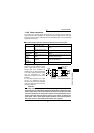
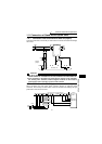
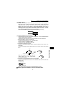
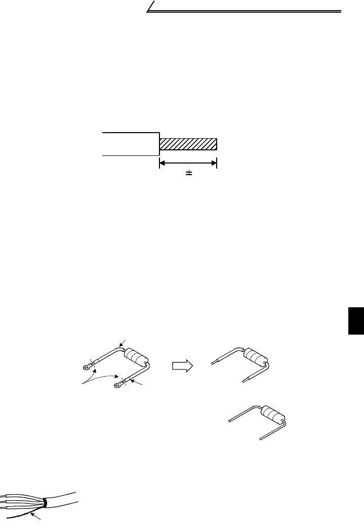
1) Use CC-Link dedicated cables and strip off their sheaths. A too long strip-off
length may cause a short circuit with the adjacent cable. A tool short strip-off
length may cause the cable to come off. Use the recommended cable. For
details, refer to the CC-Link catalog or visit the MELFANSweb home page of
Mitsubishi Electric FA Equipment Technology Information Service at http://
www.nagoya.melco.co.jp/. (Introduced in Product details (FA network) - CC-Link.)
Recommended tightening torque: 0.22N•m to 0.25N•m
Use a small screwdriver (tip thickness: 0.6mm/overall length: 3.5mm).
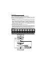
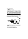
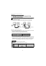
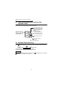
(4) Recommendation of bar terminal
For wiring of the CC-Link communication signals, two CC-Link dedicated cables
must be wired to one terminal block.
The following terminal and tool are recommended for use of bar terminals.
1) Recommended bar terminal, crimping tool
•Contact: Phoenix Contact Co., Ltd.…045-931-5602
•Bar terminal type: AI-TWIN2×0.5-8WH
•Crimping tool type: CRIMPFOX UD6, ZA3
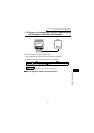
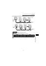
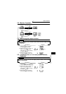
2) Connection of terminating resistor
Connect a terminating resistor between terminals DA-DB of the inverter at a
termination.
Use the terminating resistor supplied with the PLC master module after working
on it.
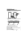
3) Connection of the shielded wires of the CC-Link dedicated cable
Connect the shielded wires of the CC-Link dedicated cable to terminal SLD after
twisting them.
Shielded wires
Note: The two SLD terminals are connected inside the inverter.
!
!!
!Refer to page 140 for details of CC-Link communication.
Note: If the resistor is not supplied with the
master module, use a 110Ω, 1/2W resistor
commercially available.
6.5mm 0.5mm
Tube
C
ut here. Cut tube.
Shielded wires