


31
Peripheral Devices
1
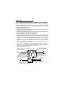
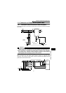
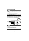
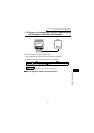
INSTALLATION AND WIRING
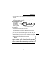
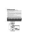
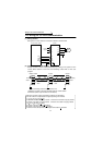
1)Calculation of equivalent capacity P0 of harmonic generating equipment
The "equivalent capacity" is the capacity of a 6-pulse converter converted from the
capacity of consumer's harmonic generating equipment and is calculated with the
following equation. If the sum of equivalent capacities is higher than the limit in
Table 3, harmonics must be calculated with the following procedure:
P0=
Σ
(Ki
×
Pi) [kVA]
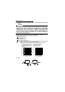
2)Calculation of outgoing harmonic current
Outgoing harmonic current=fundamental wave current (value converted from
received power voltage)
×
operation ratio
×
harmonic content
• Operation ratio:Operation ratio=actual load factor×operation time ratio during 30
minutes
• Harmonic contents: Found in Table 4.
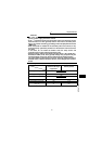
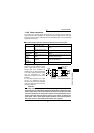
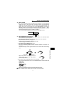
Table 2 Conversion Factors for FR-C
500
Series
Class Circuit Type Conversion Factor Ki
3
3-phase bridge
(Capacitor-smoothed)
Without reactor K31=3.4
With reactor (AC side) K32=1.8
With reactor (DC side) K33=1.8
With reactors (AC, DC sides) K34=1.4
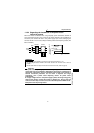
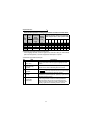
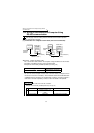
Table 3 Equivalent Capacity Limits
Received Power Voltage Reference Capacity
6.6kV 50kVA
22/33kV 300kVA
66kV or more 2000kVA
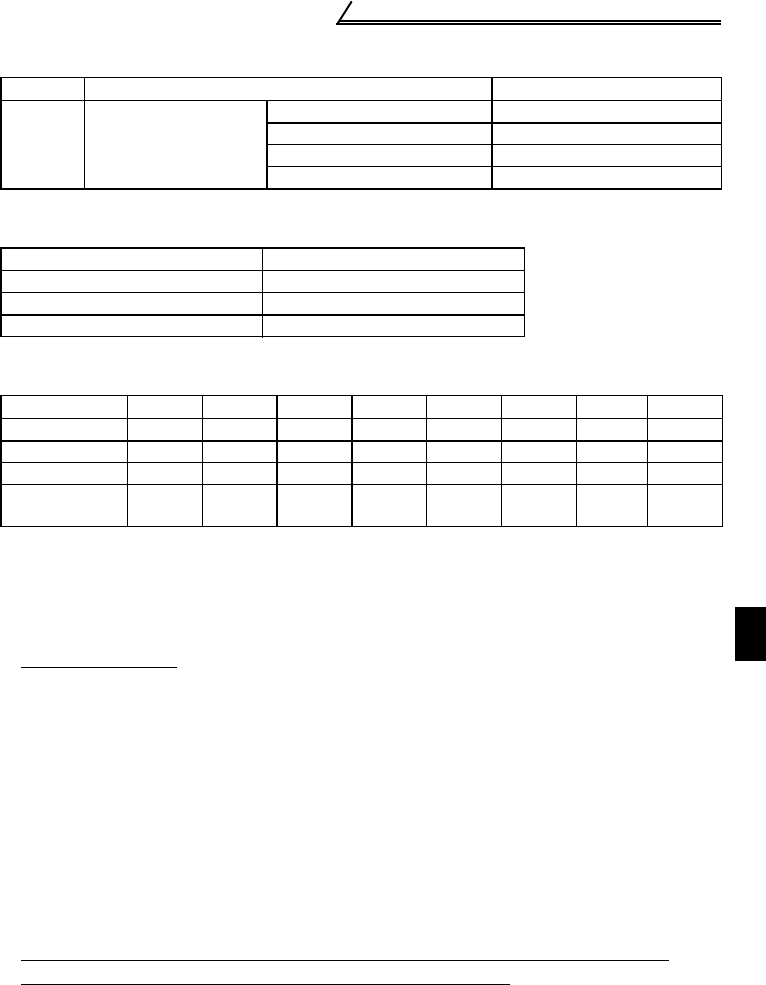
Table 4 Harmonic Content (Values at the fundamental current of 100%)
Reactor 5th 7th 11th 13th 17th 19th 23rd 25th
Not used 65 41 8.5 7.7 4.3 3.1 2.6 1.8
Used (AC side) 38 14.5 7.4 3.4 3.2 1.9 1.7 1.3
Used (DC side) 30 13 8.4 5.0 4.7 3.2 3.0 2.2
Used (AC, DC
sides)
28 9.1 7.2 4.1 3.2 2.4 1.6 1.4
Ki: Conversion factor (refer to Table 2)
Pi: Rated capacity of harmonic generating
equipment* [kVA]
i: Number indicating the conversion
circuit type
*Rated capacity: Determined by the
capacity of the applied motor and
found in Table 5. It should be
noted that the rated capacity used
here is used to calculate
generated harmonic amount and
is different from the power supply
capacity required for actual
inverter drive.