


38
Wiring of the Inverter and Computer Using RS-485
communication
1.14 Wiring of the Inverter and Computer Using
RS-485 communication
Refer to page 79 for the setting related to RS-485 communication operation.
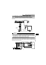
<System configuration example>
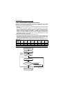
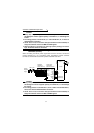
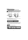
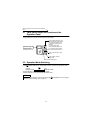
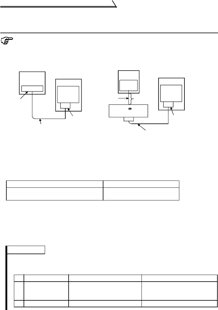
(1) Connection of a computer to the inverter (one-to-one connection)
!Computer - inverter connection cable
For a connection cable between the computer having RS-232C and the inverter
(RS-232C ⇔ RS-485 converter), refer to the table below.
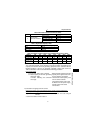
Examples of commercially available products (as of July, '02)
* You can not connect multiple inverters with a converter cable (a computer and an
inverter are one-to-one connection). As the RS-232C cable and the RS-485 cable
(10BASE-T+RJ-45 connector) are provided with a product, no need to prepare a
cable and a connector separately. Contact a maker for details of the product.
Type Maker
FA-T-RS40 *
Mitsubishi Electric Engineering
Co., Ltd
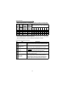
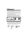
REMARKS
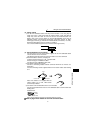
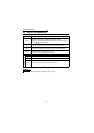
When fabricating the cable on the user side, see below.
Examples of commercially available products (as of July, '02)
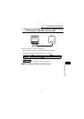
RS-485
connector
Inverter
Station No.0
Computer
RS-485
Interfase
terminal
10BASE-T cable 1)
RJ-45
connector 2)
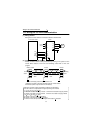
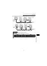
RS-485
connector
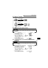
Inverter
Station No.0
Computer
10BASE-T cable 1)
RJ-45 connector 2)
RS-232C
connector
RS-232C RS-485
converter
RS-232C
cable
Maximum
15m
"
Product Type Maker
1) 10BASE-T cable
SGLPEV-T 0.5mm × 4P
* Do not use No.2 and No.8 pin
(P5S).
Mitsubishi Cable Industries, Ltd.
2) RJ-45 connector 5-554720-3 Tyco Electronics Corporation