


40
Design Information
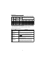
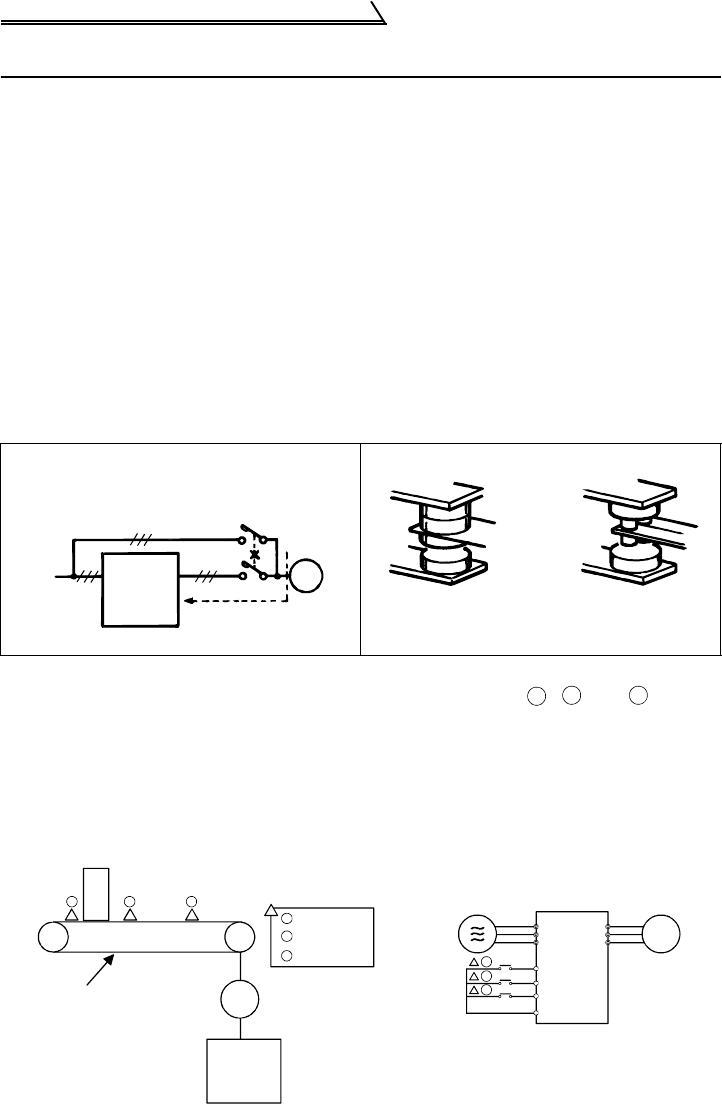
1.15 Design Information
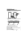
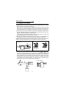
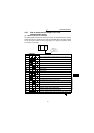
1)Provide electrical and mechanical interlocks for MC1 and MC2 which are used for
commercial power supply-inverter switch-over.
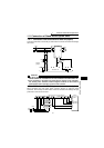
When there is a commercial power supply-inverter switch-over circuit as shown
below, the inverter will be damaged by leakage current from the power supply due to
arcs generated at the time of switch-over or chattering caused by a sequence error.
2)If the machine must not be restarted when power is restored after a power failure,
provide a magnetic contactor in the inverter's primary circuit and also make up a
sequence which will not switch on the start signal.
If the start signal (start switch) remains on after a power failure, the inverter will
automatically restart as soon as the power is restored.
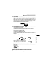
3)Since the input signals to the control circuit are on a low level, use two parallel micro
signal contacts or a twin contact for contact inputs to prevent a contact fault.
4)Do not apply a voltage to the contact input terminals (e.g. STF) of the control circuit.
5)Make sure that the specifications and rating match the system requirements.
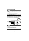
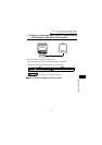
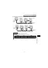
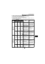
6)For use in the following application where speed control is performed using a sensor
input-based conveyor program with the signals of sensors , and entered
into the STF, STR and RL terminals, respectively, and the built-in PLC function set
for terminal function disable (D9148), the built-in PLC function is not set for terminal
function disable but for STF, STR and RL terminal function enable in the factory
setting status (Pr. 507=0) when the built-in PLC function is in a STOP status or there
is no program, and the inverter operates if any of the sensors is blocked. (Refer to
page 138 for Pr. 507 "inverter operation lock mode setting".)
1)Commercial power supply-inverter
switch-over
3)Low-level signal contacts
U
V
W
R
S
T
IM
MC2
MC1
Power
supply
Inverter
Leakage current
Interlock
Low-level
ignal contacts
Twin contact
A
B C
A
B
C
IM
R
S
T
U
V
W
IM
STF
STR
RL
SD
A
B
C
A
B
C
Work
Conveyor
Start sensor
Deceleration
sensor
Stop sensor
Motor
Inverter
<Connection diagram>
Inverter