


95
3
PARAMETERS
Description of parameters
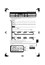
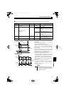
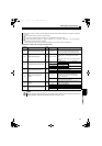
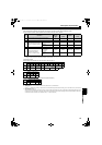
3.4.20 Current control (Pr. 82, Pr. 83)
Adjust the fluctuation range of current by setting Pr. 80.
Increasing the setting value reduces the current fluctuation caused by external disturbance.
Adjust the recovery time to the commanded current after a current fluctuation by setting Pr. 83.
Increasing the setting value shortens the recovery time from the current fluctuation caused by external disturbance.
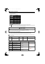
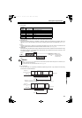
3.4.21 Wiring and configuration of PU connector
Using the PU connector, you can perform communication operation from a personal computer, etc.
When the PU connector is connected with a personal, FA or other computer by a communication cable, a user program can
run and monitor the converter or read and write to parameters.
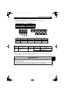
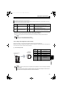
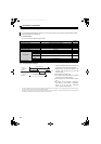
(1) PU connector pin-outs
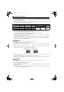
This function controls current to be as commanded.
Operation should be stable in the initial setting, but adjust the following parameters when current fluctuation occurs due
to the environment such as power source condition.
Parameter
Number
Name
Initial
Value
Setting Range Description
82
Current control proportional
gain
100% 0 to 200%
Set the proportional gain for the current control.
Increasing the setting value reduces the current fluctuation
caused by external disturbance.
83 Current control integral gain 100% 0 to 200%
Set the integral gain for the current control.
Increasing the setting value shortens the recovery time from
the current fluctuation caused by external disturbance.
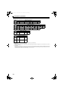
NOTE
Setting Pr. 82 too large makes the operation unstable.
Setting only Pr. 83 too large makes the operation unstable.
Pin
Number
Name Description
1) SG
Earth (ground)
(connected to terminal 5)
2) Operation panel power supply
3) RDA Converter receive+
4) SDB Converter send-
5) SDA Converter send+
6) RDB Converter receive-
7) SG
Earth (ground)
(connected to terminal 5)
8) Operation panel power supply
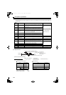
NOTE
Pins No. 2 and No. 8 provide power to the operation panel or parameter unit. Do not use these pins for RS-485
communication.
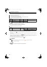
Do not connect the PU connector to the computer's LAN board, FAX modem socket or telephone modular connector.
The product could be damaged due to differences in electrical specifications.
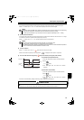
8)
to
1)
Converter
(Receptacle side)
Front view
RS-485 terminal block
cannot be used.
HC2.book 95 ページ 2012年11月19日 月曜日 午前10時52分