


49
2
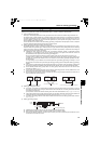
INSTALLATION AND WIRING
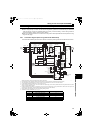
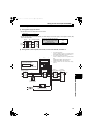
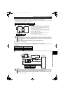
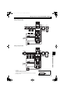
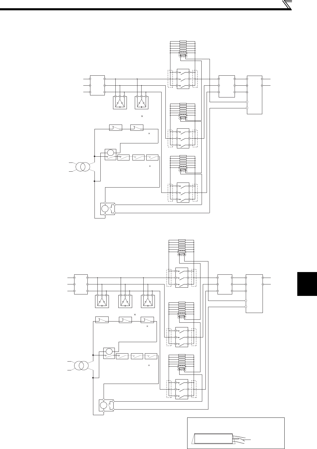
Wiring of main circuit (FR-HC2-H400K, H560K)
(2) Wiring reactor 1, filter capacitor, limit resistor, inrush current limit MC, and reactor 2
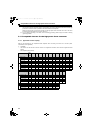
<Wiring example of 400K>
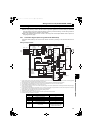
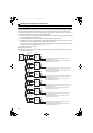
<Wiring example of 560K>
Limit resistor
0.96OHM BKO-CA1996H21 (without thermostat) 5
0.96OHM BKO-CA1996H31 (with thermostat) 1
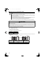
Connect them to each phase of the shorting conductors of the inrush current limit MCs.
MC shorting conductor
MC2
MC3
MC1
13
14
5
9
MC
Small
MC
Bu2
R2/
L12
S2/
L22
T2/
L32
R/
L1
S/
L2
T/
L3
R4/
L14
S4/
L24
T4/
L34
R3/
L13
S3/
L23
T3/
L33
FR-HCC2-H400K FR-HCC2-H400K
2)
3)
P/+
N/-
ROH
SD
R4/
L14
S4/
L24
T4/
L34
*1
*1
*1
*2
*2
*2
*2
*2
*2
Reactor 1
(FR-HCL21
-H400K
)
To inverter
Reactor 2
(FR-HCL22
-H400K
)
Converter
(FR-HC2
-H400K)
Limit MC1
Limit MC2
Limit MC3
1)Filter capacitors 2
Buffer relay for
filter capacitor
alarm detector
Mini relay for
filter capacitor
alarm detector
Auxiliary contact for
limit MCs (NO contact) 3
Filter capacitor alarm detector (NC contact) 2
To inverte
r
Reactor 1
(FR-HCL21
-H560K
)
1)Filter capacitors 3
Buffer relay for
filter capacitor
alarm detector
Mini relay for
filter capacitor
alarm detector
Reactor 2
(FR-HCL22
-H560K
)
Converter
(FR-HC2
-H560K)
Auxiliary contact for
limit MCs (NO contact) 3
Filter capacitor alarm detector (NC contact) 3
MC2
MC3
MC1
13
14
5
9
MC
Small
MC
Bu2
R2/
L12
S2/
L22
T2/
L32
R/
L1
S/
L2
T/
L3
R4/
L14
S4/
L24
T4/
L34
R3/
L13
S3/
L23
T3/
L33
Limit MC1
Limit MC2
Limit MC3
FR-HCC2-H560K FR-HCC2-H560K FR-HCC2-H560K
2)
3)
P/+
N/-
R4/
L14
S4/
L24
T4/
L34
ROH
SD
∗1
∗2
∗2
∗2
∗2
∗2
∗2
∗1
∗1
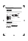
thermostat output
Limit resistor (with thermostat)
0.96OHM BKO-CA1996H31
HC2.book 49 ページ 2012年11月19日 月曜日 午前10時52分