


63
2
INSTALLATION AND WIRING
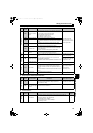
Wiring of control circuit
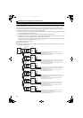
(2) Signal inputs by contactless switches
2.13.4 Wiring instructions
It is recommended to use the cables of 0.75mm
2
gauge for connection to the control circuit terminals.
If the cable gauge used is 1.25mm
2
or more, the front cover may be lifted when there are many cables running or the
cables are run improperly, resulting in an operation panel contact fault.
The wiring length should be 30m (200m for the terminal FM) at the maximum.
To minimize EMI, use shielded or twisted cables for connection to the control circuit terminals and place them away
from the main and power circuits (including the 200V relay sequence circuit).
For the cables connected to the control circuit terminals, connect their shields to the common terminal of the
connected control circuit terminal. When connecting external power supply to the terminal PC, however, connect the
shield of the power supply cable to the negative side of the external power supply. Do not directly earth (ground) the
shield to the enclosure, etc.
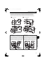
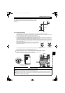
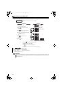
Use two or more parallel micro-signal contacts or twin contacts to prevent
a contact faults when using contact inputs since the control circuit input
signals are micro-currents.
Do not apply a voltage to the contact input terminals (e.g. RES) of the control circuit.
Always use relay coil, lamp, etc. for fault output terminals (A, B, C).
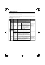
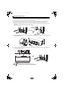
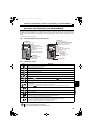
Wiring of the control circuit of the FR-HC2-75K, FR-HC2-H110K or higher
Separate the wiring of the control circuit away from the wiring of the main circuit.
Make cuts in rubber bush of the converter side and lead wires.
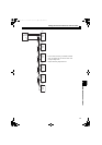
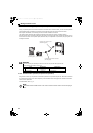
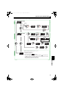
The contacted input terminals of the converter (RES, SOF, X1, X2, ROH)
can be controlled using a transistor instead of a contacted switch as shown
on the right.
External signal input using transistor
CAUTION
Do not connect anything to the free terminal (NC) of the control circuit.
Using the terminal may cause a damage to the converter and the inverter.
Always connect the terminal RDY of the converter to the terminal MRS or the inverter terminal of which X10 signal is
assigned to. Also, always connect the terminal SE of the converter to the terminal SD of the inverter. If these are not
connected, the converter may be damaged.
+24V
RES, etc
SD
Converter
Micro signal contacts Twin contacts
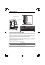
<Wiring>
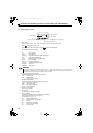
Rubber bush
(view from the inside)
Make cuts along the lines inside with
a cutter knife and such.
HC2.book 63 ページ 2012年11月19日 月曜日 午前10時52分