


45
2
INSTALLATION AND WIRING
Wiring of main circuit (FR-HC2-H280K)
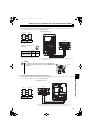
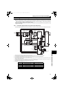
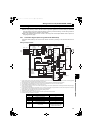
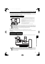
(4) Wiring example of converter and inverter
These units should be connected to transmit commands from the converter to the inverter securely.
Connection method differs depending on the inverter series. Refer to the Instruction Manual of the inverter when
connecting. Refer to the below table for the wiring length.
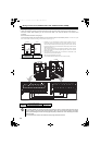
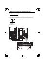
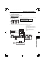
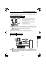
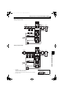
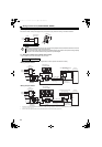
(5) Wiring reactor 1 and converter
Supply power to the power detecting terminals (R/L1, S/L2, T/L3) separately from the main circuit wiring.
Switch the tap (V1, V2, V3) of the MC power supply stepdown transformer according to the input power supply voltage as shown
in the below table.
Connect the MC start command terminals (88R, 88S) to the MC for the inrush current limit MC (for three phases) through the buffer
relay.
Across terminals P and P / terminals N and N 50m or less
Other control signal lines 30m or less
NOTE
The converter operates as a common converter. Use terminals P/+ and N/- to connect it with the inverter. Do not
connect anything to the inverter power input terminals R/L1, S/L2, and T/L3. Incorrect connection to the inverter
power input will damage the inverter. Connecting opposite polarity of terminals P/+ and N/- will damage the inverter
and the converter.
Do not connect the DC reactor to the inverter when using a high power factor converter.
Power Supply Voltage Switching Tap Position
380V or more, less than 400V V1
400V or more, 440V or less V2
More than 440V, 460V or less V3
NOTE
The terminal R/L1, S/L2, and T/L3 of the converter are control terminals to detect power supply phases of the power
supply. The voltage phases of the terminals R4/L14, S4/L24 and T4/L34 and the terminals R/L1, S/L2 and T/L3 must be
matched. If these terminals are not connected correctly, the converter does not operate properly.
If the inverter is operated without connecting the terminals R/L1, S/L2 and T/L3 of the converter to the power supply,
the converter will be damaged.
Inverter
∗3
∗1
∗2
Control
circuit
Converter
(FR-HC2
-H280K)
P/+
N/-
P/+
N/-
R4/L14
S4/L24
T4/L34
X10
RES
SD
RDY
RSO
SE
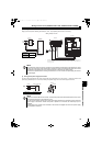
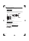
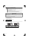
Installation of a fuse is recommended to avoid the damage to spread in case
of an inverter failure. Select a fuse according to the motor capacity. When
using a motor, of which the capacity is smaller than the inverter capacity by
two ranks or more, select the fuse capacity according to the inverter capacity.
Refer to the fuse selection table on page 11, 13.
When connecting several inverters, the wire gauge of terminal P/+ and N/-
should be same as the wire gauge of the inverter's power supply side. (Refer
to the Instruction Manual of the inverter.)
The function of the inverter terminal, which is connected to the terminal RDY
of the converter, needs to be set at the inverter side.
Refer to the Instruction Manual of the inverter.
Do not insert MCCB between terminals P/+ and N/- (P and P, N and N).
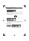
Cable gauge for
the control circuit
0.75 to 2mm
2
Converter
(FR-HC2-H280K)
Limit MC
Buffer relay for driving MCs
(SR-N4)
Stepdown
transformer (1PH 630VA)
Reactor 1
(FR-HCL21-H280K)
88R
R/L1
S/L2
T/L3
88S
R1/L11
S1/L21
R/
L1
S/
L2
T/
L3
R/L1
S/L2
R5/L15
S5/L25
Power
Supply
MC
MC
Bu1
R2/
L12
S2/
L22
T2/
L32
V1
AC410V
V2
AC430V
V3
AC470V
Total wiring length 10m or less
Cable gauge
1.25mm
2
HC2.book 45 ページ 2012年11月19日 月曜日 午前10時52分