


2
Pre-operation instructions
1.1 Pre-operation instructions
Incorrect handling may cause the equipment to operate improperly, its life to be reduced considerably, and in the worst case,
the converter and inverter to be damaged. Please handle the unit properly in accordance with the information on each section
as well as the precautions and instructions of this manual.
1.1.1 Features of FR-HC2 (high power factor converter)
Power supply harmonics generated from the converter part of an inverter may affect devices including a dynamo and a static
capacitor. Power supply harmonics differ from noise and leakage current in their generating source, frequency range and
transmission method. Power supply harmonic may be suppressed by using this converter, allowing the compliance with the
harmonic suppression guideline issued by the former Japanese Ministry of International Trade and Industry (currently the
Ministry of Economy, Trade and Industry). Conversion factor of the converter is K5=0 in the self-excitation three-phase bridge
circuit.
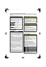
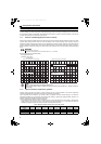
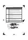
Power supply harmonic suppression effect
(Example) FR-HC2-7.5K
(Condition) Load: 100%
Power factor: 1
1.1.2 Japanese harmonic suppression guideline
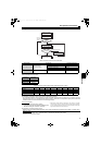
Harmonic currents flow from the inverter to a power receiving point via a power transformer. The harmonic suppression
guideline was established to protect other consumers from these outgoing harmonics.
The all capacities and all models of the inverters used by the specific consumers became subject to the Harmonic
Suppression Guideline for the Consumers Who Receive High-voltage or Special High-voltage (hereafter referred to as
"Harmonic Suppression Guideline for Specific Consumers").
[Harmonic suppression guideline for specific consumers]
This guideline sets the maximum values of outgoing harmonic currents generated from a high-voltage or specially high-
voltage consumer who will install, add or renew harmonic generating equipment. If any of the maximum values are
exceeded, this guideline requires the consumer to take certain suppression measures.
REMARKS
Inverter parameters must be set.
The parameter settings differ by the inverter series. Refer to page 55 for details.
NOTE
When the load is light, harmonic suppression effect declines.
When the power supply voltage is unstable, harmonics from electric power system flow in, making the harmonic
current larger.
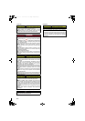
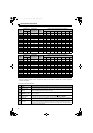
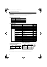
Table 1 Maximum outgoing harmonic current per 1kW contract
Received Power
Voltage
5th 7th 11th 13th 17th 19th 23rd Over 23rd
6.6kV 3.5 2.5 1.6 1.3 1.0 0.9 0.76 0.70
22kV 1.8 1.3 0.82 0.69 0.53 0.47 0.39 0.36
33kV 1.2 0.86 0.55 0.46 0.35 0.32 0.26 0.24
Input phase voltage(100V/div)
Input phase current
(50A/div)
[When the converter is not connected]
Input phase voltage(100V/div)
Input phase current
(50A/div)
[When the converter is connected]
HC2.book 2 ページ 2012年11月19日 月曜日 午前10時52分