


36
Wiring of main circuit (FR-HC2-7.5K to 75K, FR-HC2-H7.5K to H220K)
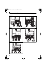
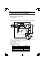
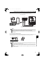
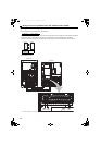
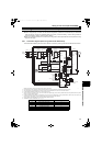
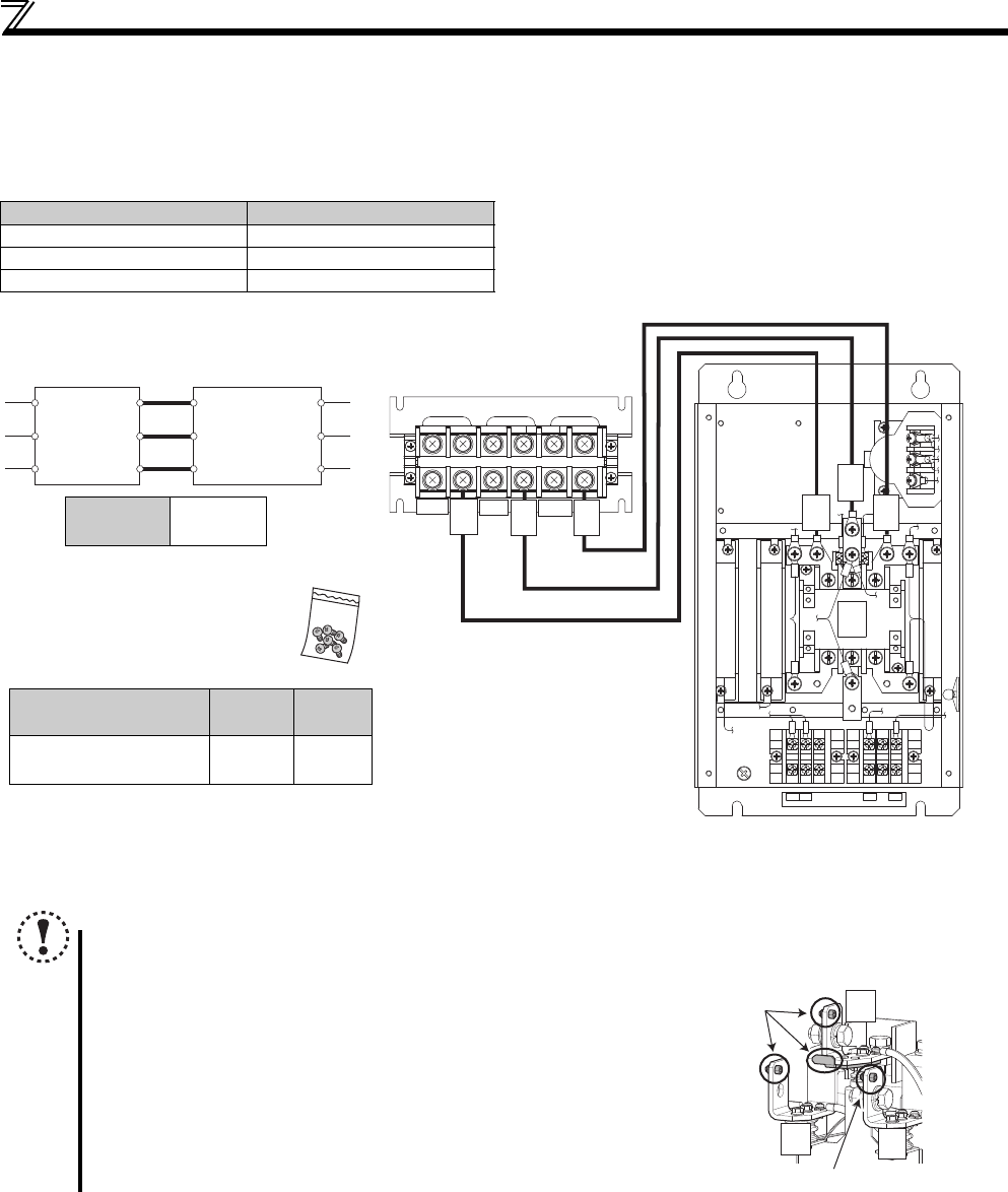
(2) Wiring of reactor 1 and outside box
• Cable size differs by the capacity. Select an appropriate cable by referring to 2.6.3 Cable sizes of the main control circuit
terminals and earth (ground) terminals (refer to page 31) and perform wiring.
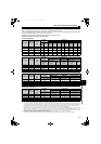
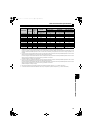
• The 400V class outside box is equipped with a MC power supply stepdown transformer. Switch the tap (V1, V2, V3) of the
stepdown transformer according to the input power supply voltage as shown in the table below.
Power Supply Voltage Switching Tap Position
380V or more, less than 400V V1
400V or more, 440V or less V2
More than 440V, 460V or less V3
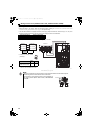
<Wiring example of 7.5K>
The terminal arrangement differs by capacity. Check the terminal arrangement on 6.3
Outline dimensions (refer to page 150).
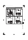
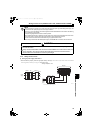
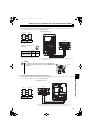
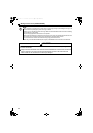
NOTE
• Because the reactor heats up, install the reactor in a place where the outside box will be unaffected by heat.
• Perform wiring where the wire sheath does not touch the reactor.
• Do not remove or wire the whirl-stop (shown on the right diagram) of
the crimping terminals (R2/L12, S2/L22, T2/L32) of FR-HCB2-H160K
and H220K.
Reactor 1
Outside box
R3/L13
S3/L23
T3/L33
R/L1
S/L2
T/L3
R2/L12 R2/L12
S2/L22 S2/L22
T2/L32 T2/L32
Total wiring
length
10m or less
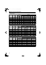
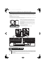
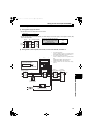
• Outside box terminal screws
(accessory)
Use the enclosed screws (M5) for the wiring of FR-
HCB2-7.5K, 15K and FR-HCB2-H7.5K to H30K.
Model
Screw
size
Quantity
FR-HCB2-7.5K, 15K
FR-HCB2-H7.5K to H30K
M5 6
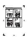
Reactor 1
ROH1
88R 88S
ROH2
(1)
(2)
(3)
R3
S3
T3
(88S)(88R)
(ROH1) (ROH2)
Outside box
R/L1
S/L2
T/L3
R2/
L12
S2/
L22
T2/
L32
R2/
L12
S2/
L22
T2/
L32
R2/
L12
S2/
L22
T2/
L32
Whirl-stop
Whirl-stop
HC2.book 36 ページ 2012年11月19日 月曜日 午前10時52分