


44
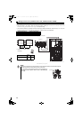
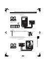
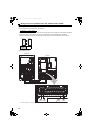
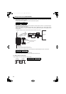
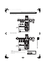
Wiring of main circuit (FR-HC2-H280K)
1) Filter capacitor
Install three filter capacitors in parallel to the output side of the reactor 1 or to the input side of the inrush current limit
MC as shown in the above diagram.
Use the cable shown in the table below for the connection of filter capacitor.
2) Limit resistor, inrush current limit MC
Install a pair of a limit resistor and a inrush current limit MC to the output side of the reactor 1, and install another pair
of those to the input side of the reactor 2.
Install the limit resistor to the appended terminal block. Short a terminal block with a terminal block shorting
conductor, and use them as a pair in each phase. Connect the appended terminal blocks to the appended inrush
current limit MCs.
Use the cable shown in the below table for the connection of each phase between the reactor 1 and reactor 2.
3) Connecting limit resistor thermostats to the converter
Connect a limit resistor thermostat across the converter terminals ROH and SD.
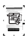
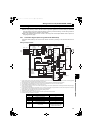
(3) Wiring reactor 2 and converter
Use the cable shown in the below table for the connection.
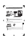
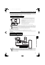
Cable gauge
60mm
2
Wiring length 2m or less
Cable gauge
200mm
2
Total wiring length 10m or less
Cable gauge
200mm
2
Total wiring length 10m or less
∗2 Include one appended limit resistor with thermostat in the S-phase.
Wire to the
terminal block (22mm
2
)
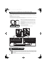
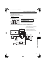
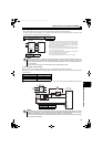
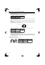
Connection example of inrush current limit MCs and limit resistors (of one phase)
Crimping
terminal
Crimping
terminal
MC conductor
Wire to the
terminal block
Power cable
∗1 Make sure that the power cable touches the MC conductor.
Inrush current
limit MC
Inrush
current
limit MC
∗1
∗2
Power cable
Appended terminal block
shorting conductor
Appended
terminal block
Reactor 2
(FR-HCL22
-H280K
)
Converter
(FR-HC2
-H280K)
R3/
L13
S3/
L23
T3/
L33
R4/
L14
R4/
L14
S4/
L24
S4/
L24
T4/
L34
T4/
L34
P/+
N/-
HC2.book 44 ページ 2012年11月19日 月曜日 午前10時52分