


56
Wiring of several inverters to one converter
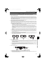
2.12 Wiring of several inverters to one converter
Up to ten inverters can be connected to one converter. Be sure to use a converter with the capacity higher than the total
capacities of inverters. Additionally, the total capacity of the inverters needs to be higher than half the converter capacity.
If the total inverter capacity is less than half the converter capacity, the converter can be used as a common converter or a
regenerative converter. However, it's harmonic suppression effect reduces.
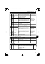
(1) Junction terminals or cross wiring are used to connect several inverters, so carefully select the wire gauge. Start adding
the inverter capacities from the furthest inverter.
(2) When connecting several inverters, connect starting with the inverter with the highest capacity.
(3) Installation of a fuse, which corresponds with each motor capacity, is recommended for each inverter when connecting
several inverters to one converter. Select a fuse according to the motor capacity.
When using a motor, of which capacity is smaller than the inverter capacity by two ranks or more, select the converter
capacity according to the inverter capacity. (Refer to page 11 and 13.)
(4) Keep the total wiring length within 50m.
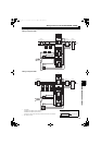
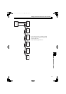
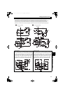
Main circuit wiring example
The following diagram shows a connection example when connecting six inverters in total (FR-A720-30K, 15K, 5.5K, 2.2K,
1.5K, and 0.75K) to FR-HC2-55K.
FR-HC2
-55K
A720
30K
A720
15K
A720
5.5K
A720
2.2K
A720
1.5K
A720
0.75K
P
N
P
N
P
N
P
N
P
N
P
N
1st inverter
P
N
Junction terminal 1
Junction terminal 2
Junction terminal 3
Junction terminal 4
Junction terminal 5
Junction terminal 6
1)
2)
4)
6)
8)
10)
3)
5)
7)
9)
11)
12)
INV1
INV2
INV3
INV4
INV5
INV6
Fuse
Motor
Motor
30kW
15kW
5.5kW
2.2kW
1.5kW
0.75kW
Motor
Motor
Motor
Motor
1) Wire gauge between FR-HC2 and the junction terminal 1 is 100mm
2
according to the FR-HC2 capacity.
2) Wire gauge between the junction terminal 1 and the inverter is 60mm
2
because the inverter capacity is 30K.
2nd inverter
3) Wire gauge between the junction terminal 1 and junction terminal 2 can be
calculated as follows: 15+5.5+2.2+1.5+0.75=24.95K, and 24.95K rounds
up to 30K, so the wire gauge is 60mm
2
.
4) The Wire gauge between the junction terminal 2 and the inverter is 22mm
2
because the inverter capacity is 15K.
3rd inverter
5) Wire gauge between the junction terminal 2 and junction terminal 3 can be
calculated as follows: 5.5+2.2+1.5+0.75=9.95K, and 9.95K rounds up to
11K, so the wire gauge is 14mm
2
.
6) Wire gauge between the junction terminal 3 and the inverter is 14mm
2
because the inverter capacity is 5.5K.
4th inverter
7) Wire gauge between the junction terminal 3 and junction terminal 4 can be
calculated as follows: 2.2+1.5+0.75=4.45K, and 4.45 K rounds up to 5.5K,
so the wire gauge is 5.5mm
2
.
8) Wire gauge between the junction terminal 4 and the inverter is 2mm
2
because the inverter capacity is 2.2K.
5th inverter
9) Wire gauge between the junction terminal 4 and junction terminal 5 can
be calculated as follows: 1.5+0.75=2.25K, and 2.25K rounds down to
2.2K, so the wire gauge is 2mm
2
.
10) Wire gauge between the junction terminal 5 and the inverter is 2mm
2
because the inverter capacity is 1.5K.
6th inverter
11) Wire gauge between the junction terminal 5 and junction terminal 6 is
2mm
2
because the inverter capacity is 0.75K.
12) Wire gauge between the junction terminal 6 and the inverter is 2mm
2
because the inverter capacity is 0.75K.
Motor
HC2.book 56 ページ 2012年11月19日 月曜日 午前10時52分