


47
2
INSTALLATION AND WIRING
Wiring of main circuit (FR-HC2-H400K, H560K)
2.9 Wiring of main circuit (FR-HC2-H400K, H560K)
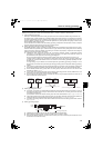
Perform wiring securely to conform with the harmonic suppression guideline of the former Ministry of International
Trade and Industry (currently the Japanese Ministry of Economy, Trade and Industry). Incorrect wiring causes the
converter to display an alarm or causes an fault or damage.
Refer to the Instruction Manual of each inverter for the wiring of the inverter. Special attention must be paid to the
wiring length and wire gauge.
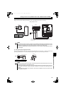
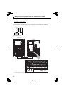
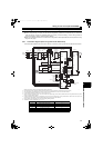
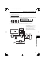
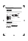
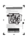
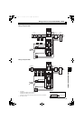
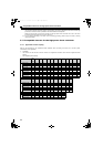
2.9.1 Connection diagram (when using with the FR-A700 series)
Connection method differs by the inverter series. Perform connection by referring to the Instruction Manual of the
inverter.
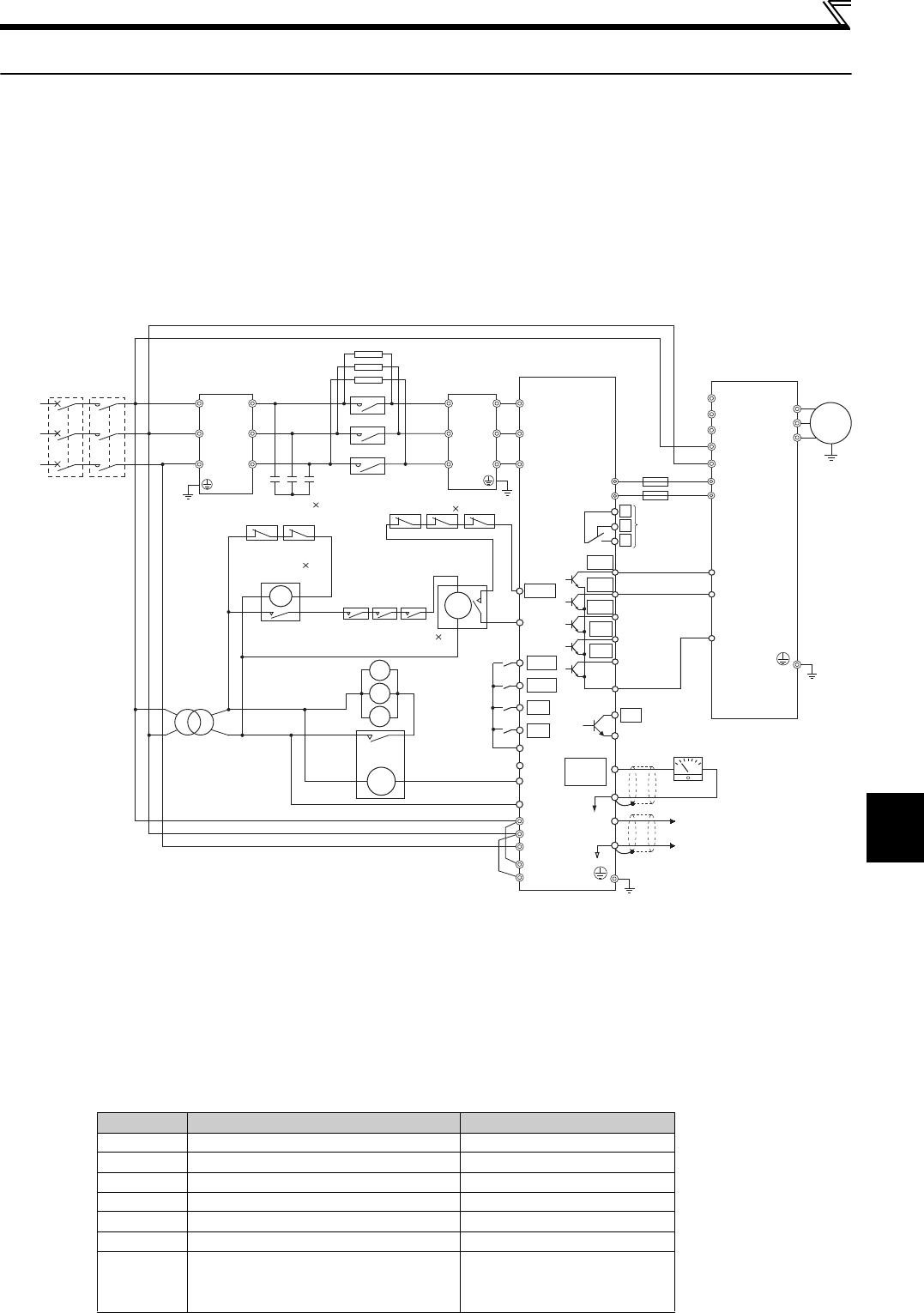
<Wiring example of 400K>
Do not connect anything to the inverter power input terminals R/L1, S/L2, and T/L3. Incorrect connection will damage the inverter. Connecting opposite
polarity of terminals P and N will damage the converter and the inverter.
Use input terminal function selection to assign the terminal used for X10 signal. (Refer to the Instruction Manual of the inverter.)
The power phases of the terminals R4/L14, S4/L24, and T4/L34 and the terminals R/L1, S/L2, and T/L3 must be matched.
Do not insert MCCB between terminals P/+ and N/- (P and P, N and N).
Always connect the terminal R, S, and T of the converter to the power supply. If the inverter is operated without connecting the terminals to the power supply,
the converter will be damaged.
Do not insert MCCB or MC between (1) (terminal R/L1, S/L2, T/L3 input of the converter) and (3) (terminal R4/L14, S4/L24, T4/L34 input of the converter) of
the above diagram. It will not operate properly (except for the inrush current limit MC).
Securely perform grounding (earthing) by using the grounding (earthing) terminal.
Installation of a fuse is recommended. (Refer to page 11)
Connect three sets consisting of one filter capacitor and one filter capacitor alarm detector for 560K.
For 560K, install a set of three MCs to each phase.
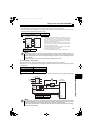
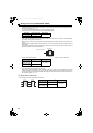
Number Wiring Refer to page
(1) Power supply and reactor 1 48
(2) Reactor 1 and reactor 2 49
(3) Reactor 2 and converter 50
(4) Converter and inverter 51
(5) Reactor 1 and converter 51
(6) Power supply and inverter 52
(7)
Filter capacitor alarm detector
and converter
52
(Instruction Manual of the filter
capacitor alarm detector)
Inverter
Converter
(FR-HC2)
Filter capacitors 2
(FR-HCC2)
Limit resistor
Motor
Reactor 1
(FR-HCL21)
Power
Supply
MCCB
∗7
Limit MC
Buffer relay for driving MCs
MC power
supply
stepdown
transformer
Mini relay for filter
capacitor alarm detector
Buffer relay for
filter capacitor
alarm detectors
Reactor 2
(FR-HCL22)
Auxiliary contact for
limit MCs (NO contact) 3
Filter capacitor
alarm detector
(NC contact) 2
Limit resistor (with thermostat)
(NC contact) 3
MC1
MC2
MC3
R1/L11
S1/L21
R4/L14
R/L1
S/L2
T/L3
S4/L24
T4/L34
R4/
L14
S4/
L24
T4/
L34
R3/
L13
S3/
L23
T3/
L33
R2/
L12
S2/
L22
T2/
L32
R/
L1
S/
L2
T/
L3
MC
U
V
W
88R
R/L1
S/L2
T/L3
88S
R1/L11
S1/L21
MC
Bu1
MC1
MC2
MC3
ROH
SD
MC2
MC3
MC
Small
MC
Bu2
MC1
SOF
X1
X2
RES
SD
P/+P/+
N/-
N/-
X10
RES
SD
RDY
RSO
SE
CVO
Y1
Y2
SE2
FM
SD
Indicator
+
-
(-)
(+)
AM
5
A
B
C
PC
Inrush current
limit resistor
overheat
protection
Reset
Contact input
common
Converter stop
Monitor switching
Monitor switching
Contact input
common
24VDC power supply
(External transistor common)
Fuses
Relay output
(fault output)
Inverter run
enable signal
Converter reset
During converter run
Multi-purpose
output 1
Multi-purpose
output 2
Multi-purpose
output 3
Open collector output
common
Open collector output common
Analog signal output
(0 to 10VDC)
PU
connector
Y3
Earth
∗4
∗2
∗1
∗3
∗7
∗5
∗7
∗7
∗8
(Ground)
∗9
∗9
∗10
(1)
(2)
(3)
(4)
(5)
(6)
(7)
HC2.book 47 ページ 2012年11月19日 月曜日 午前10時52分