


190
(2) Low Voltage Directive
We have self-confirmed our converters as products compliant to the Low Voltage Directive (Conforming standard EN
61800-5-1) and affix the CE marking on the converters.
Outline of instructions
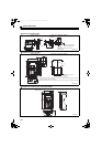
Do not use an earth leakage circuit breaker as an electric shock protector without connecting the equipment to the earth.
Connect the equipment to the earth securely.
Wire the earth (ground) terminal independently. (Do not connect two or more cables to one terminal.)
Use the cable sizes on page 31, 48 under the following conditions.
Surrounding air temperature: 40°C maximum
If conditions are different from above, select appropriate wire according to EN60204 ANNEX C TABLE 5.
Use a tinned (plating should not include zinc) crimping terminal to connect the earth cable. When tightening the screw,
be careful not to damage the threads.
For use as a product compliant with the Low Voltage Directive, use PVC cable on page 31, 48.
Use the moulded case circuit breaker and magnetic contactor which conform to the EN or IEC Standard.
When using an earth leakage circuit breaker, use a residual current operated protective device (RCD) of type B (breaker
which can detect both AC and DC). If not, provide double or reinforced insulation between the converter and other
equipment, or put a transformer between the main power supply and converter.
Use the inverter under the conditions of overvoltage category II (usable regardless of the earth (ground) condition of the
power supply), overvoltage category III (usable with the earthed-neutral system power supply, 400V class only) specified
in IEC664.
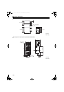
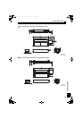
Mount the converter (including all peripheral devices such as outside box, reactor 1, and reactor 2) to the enclosure
panel of IP54 or higher.
On the input and output of the converter, use cables of the type and size set forth in EN60204 Appendix C.
The operating capacity of the relay outputs (terminal symbols A, B, C) should be 30VDC, 0.3A. (Relay output has basic
isolation from the inverter internal circuit.)
Control circuit terminals on page 34, 47 are safely isolated from the main circuit.
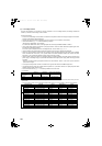
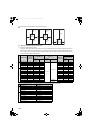
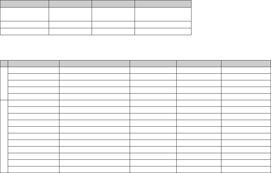
Environment
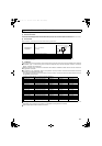
Provide the Class T fuse or a fuse with faster shutoff speed, which is UL and cUL listed, for branch circuit protection.
Running In Storage During Transportation
Surrounding air
temperature
-10°C to +50°C -20°C to +65°C -20°C to +65°C
Humidity 90% RH or less 90% RH or less 90% RH or less
Maximum Altitude 1000m 1000m 10000m
Details are given in the technical information "Low Voltage Directive Conformance Guide" (BCN-A21041-203). Please contact your sales
representative.
Converter model Fuse type Cat. No Manufacturer Rating
200V class
FR-HC2-7.5K UL Recognized High Speed 170M1414 Bussmann 50A, 700 Vac
FR-HC2-15K UL Recognized High Speed 170M1416 Bussmann 80A, 700 Vac
FR-HC2-30K UL Recognized High Speed 170M2666 Bussmann 160A, 700 Vac
FR-HC2-55K UL Recognized High Speed 170M2669 Bussmann 315A, 700 Vac
FR-HC2-75K UL Recognized High Speed 170M2671 Bussmann 400A, 700 Vac
400V class
FR-HC2-H7.5K UL Recognized High Speed 170M1411 Bussmann 25A, 700 Vac
FR-HC2-H15K UL Recognized High Speed 170M1414 Bussmann 50A, 700 Vac
FR-HC2-H30K UL Recognized High Speed 170M1416 Bussmann 80A, 700 Vac
FR-HC2-H55K UL Recognized High Speed 170M2666 Bussmann 160A, 700 Vac
FR-HC2-H75K UL Recognized High Speed 170M2667 Bussmann 200A, 700 Vac
FR-HC2-H110K UL Recognized High Speed 170M2669 Bussmann 315A, 700 Vac
FR-HC2-H160K UL Recognized High Speed 170M2671 Bussmann 400A, 700 Vac
FR-HC2-H220K UL Recognized High Speed 170M3122 Bussmann 550A, 700 Vac
FR-HC2-H280K UL Recognized High Speed 170M4117 Bussmann 700A, 700 Vac
FR-HC2-H400K UL Recognized High Speed 170M5116 Bussmann 1000A, 700 Vac
FR-HC2-H560K UL Recognized High Speed 170M6117 Bussmann 1400A, 700 Vac
HC2.book 190 ページ 2012年11月19日 月曜日 午前10時52分