


62
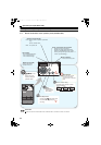
Wiring of control circuit
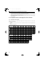
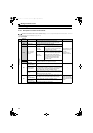
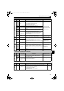
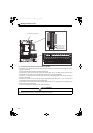
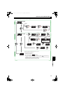
2.13.3 Control circuit terminal layout
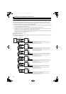
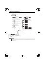
(1) Common terminals of the control circuit (SD, 5, SE, SE2)
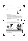
Terminals SD, 5, SE, and SE2 are all common terminals (0V) for I/O signals and are isolated from each other. Do not earth
(ground) these terminals.
Avoid connecting the terminal SD and 5 and the terminal SE and 5.
Terminal SD is a common terminal for the contact input terminals (RES, SOF, X1, X2, ROH) and the pulse train output
terminal (FM). The open collector circuit is isolated from the internal control circuit by photocoupler.
Terminal 5 is a common terminal for the analog output terminal AM. It should be protected from external noise using a
shielded or twisted cable.
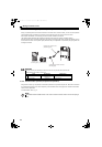
Terminal SE is a common terminal for the open collector output terminal (RDY, RSO, CVO, Y1, Y2). The contact input
circuit is isolated from the internal control circuit by photocoupler.
Terminal SE2 is a common terminal for the open collector output terminal (Y3). The contact input circuit is isolated from the
internal control circuit by photocoupler.
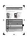
Do not connect anything to the free terminal (NC) of the control circuit.
CAUTION
Do not connect anything to the free terminal (NC) of the control circuit.
Using the terminal may cause a damage to the converter and the inverter.
5
IRL
NC
IRH
Y3
SE2
NC
TR1
TR2
IRO
MCO
RDO
RDI
MCI
Terminal screw size: M3.5
Terminal screw size: M3
Dedicated board for FR-HC2
Terminals 5, IRH, IRL, TR1,
TR2, IRO, MCO, RDO, RDI,
and MCI are for manufacturer
setting. Keep them open.
88R
88S
A
CVORSORDY
NCNCNC
SENCNCNC
B C NC AM
PCPCY1
PCY2SESE SDSDSDFM
5X1X2
ROHSOFRES
NC
HC2.book 62 ページ 2012年11月19日 月曜日 午前10時52分