


113
Description of parameters
3
PARAMETERS
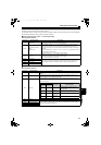
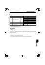
(6) Details of the remote register
The following device numbers are for the station number 1.
For the station number 2 and later, the device numbers are different. (Refer to the manual for the CC-Link master module for
the correspondence between device numbers and station numbers.)
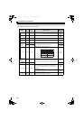
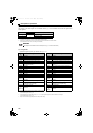
Remote register (master module converter (FR-A7NC))
Remote register definition
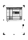
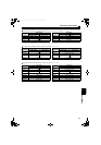
Remote register (converter (FR-A7NC) master module)
Remote register definition
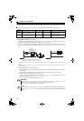
Device No. Remote register Description
RWw0
Monitor code1/
Monitor code 2
Set the monitor code of the monitoring item. (Refer to page 108) Turning ON the RYC signal
after setting this register sets the monitor data to RWr0/RWr1.
RWw2
Link parameter extended
setting/
Instruction code
Set an instruction code (Refer to page 114) for an operation such as parameter read/write,
alarm reference, and alarm clear. Turning ON the RYF signal after setting this register
executes the instruction code. The RXF signal turns ON after the instruction code execution is
completed.
When a value other than "0" is set to Pr. 544 CC-Link extended setting, upper 8 bits are used for
the link parameter extended setting.
Example) Reading of Pr. 300 The instruction code is 0300H.
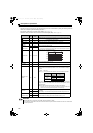
RWw3 Write data
Set data for the instruction code set in RWw2. (When required)
Turn ON the RYF signal after setting RWw2 and this register.
Set "0" when the write data is not required.
RWw4 Monitor code 3
Set the monitor code of the monitoring item. Turning ON the RYC signal after setting this
register sets the monitor data to RWr. ( indicates a register number. (RWr4 to 7))
RWw5 Monitor code 4
RWw6 Monitor code 5
RWw7 Monitor code 6
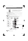
Device No. Remote register Description
RWr0 First monitor value
Turning ON the RYC signal sets the monitor value to the lower 8 bits of the specified monitor code
(RWw0).
RWr1 Second monitor value
Turning ON the RYC signal sets the monitor value to the upper 8 bits of the monitor code
(RWw0) except when "0" was set to the upper 8 bits.
RWr2 Reply code
Turning ON the RYF signal sets the reply code, which corresponds to the instruction code of
RWw2. The value "0" is set for a normal reply, and a value other than "0" is set for errors with
data, mode, and other.
RWr3 Read data In a normal reply, a replay code for the instruction code is set.
RWr4 Third monitor value
Turning ON the RYC signal sets the monitor values to the specified monitor code (RWw). (
indicates a register number. (RWw4 to 7))
RWr5 Fourth monitor value
RWr6 Fifth monitor value
RWr7 Sixth monitor value
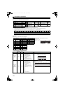
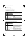
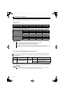
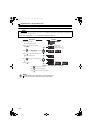
Reply code
Description Fault description
When
Pr. 554 = 0
When
Pr. 554 0
H0000 H00 Normal
No fault (Instruction codes are executed
without any fault.)
H0001 H01
Write mode
fault
Parameter write is attempted when the
converter is running.
H0002 H02
Parameter
selection fault
Unregistered code is set.
H0003 H03
Setting range
fault
Set data exceeds the permissible range.
HC2.book 113 ページ 2012年11月19日 月曜日 午前10時52分