


59
2
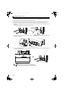
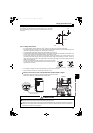
INSTALLATION AND WIRING
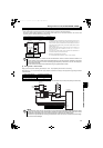
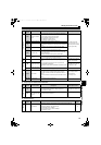
Wiring of control circuit
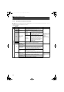
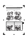
(2) Output signal
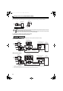
(3) Output signals of FR-HC2 dedicated board
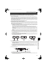
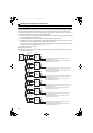
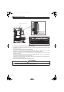
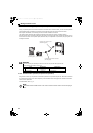
(4) Communication
USB connector and RS-485 terminal block cannot be used.
Type
Terminal
Symbol
Terminal Name Description Rated Specifications
Open collector
RDY
Inverter run enable
signal
Turns ON at alarm occurrence and reset (RES) signal input.
Connect this terminal to the terminal MRS or a terminal where
the X10 signal is assigned to in the inverter.
Turning ON RDY signal stops the inverter.
RYD signal OFF: Inverter can run
RYD signal ON: Inverter cannot run
Permissible load 24VDC
(27VDC maximum) 0.1A (A
voltage drop is 2.8V maximum
when the signal is ON.)
CVO
During converter run Signal is output during harmonic suppression.
Y1
Multi-purpose output
1
Output item: OL signal (overload alarm) (initial setting)
Turns ON at an occurrence of overcurrent (150% overload or
more).
Y2
Multi-purpose output
2
Output item: PHS signal (power phase detection) (initial
setting)
Turns ON when power phase detection is locked.
RSO
Converter reset
Turns ON at a converter reset (RES-ON).
Connect this terminal to the inverter terminal of which RES
signal is assigned to.
Reset the connected inverter by turning ON the RSO.
SE
Open collector output
common
Common terminal for the terminals RDY, CVO, OL, Y1, Y2
Connect it to the inverter terminal SD (sink logic).
Pulse
FM
For meter
Select one monitor item from multiple monitor items such as
input current and bus voltage. Not output during a converter
reset.
The output signal is proportional to the magnitude of the
corresponding monitoring item.
Monitor item can be switched by ON/OFF of terminals X1 and
X2.
Permissible load current 2mA
At rated input current of the
converter: 1440 pulses/s
Analog
AM
Analog signal output
Output signal 0 to 10VDC
Permissible load current 1mA
Load impedance 10k
5
Analog signal output
common
Common terminal for analog signal output
Relay
A, B, C
Fault contact
1 changeover contact output indicates that the converter's
protective function is activated and the output is stopped.
Fault: No conduction across B and C (Conduction across A
and C),
Normal: Conduction across B and C (No conduction across A
and C)
Contact capacity AC230V
0.3A
(Power factor=0.4)
30VDC output 0.3A
88R, 88S
MC connection
terminal
Controls the MC for the limit resistor.
Type
Terminal
Symbol
Terminal Name Description Rated Specifications
Open collector
Y3
Multi-purpose output
3
Output item: Y5 signal (output voltage match) (initial setting)
Turns ON when the detected bus voltage equals to the
commanded bus voltage.
Permissible load: 24VDC 0.1A
SE2
Open collector output
common
Common terminal for terminal Y3
Type
Terminal
Symbol
Terminal Name Description
Refer to
page
RS-485
PU connector
With the PU connector, communication can be made through RS-485. (for
connection on a 1:1 basis only)
Conforming standard : EIA-485 (RS-485)
Transmission format : Multidrop
Communication speed : 4800 to 38400bps
Overall length : 500m
95
HC2.book 59 ページ 2012年11月19日 月曜日 午前10時52分