


111
Description of parameters
3
PARAMETERS
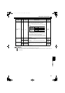
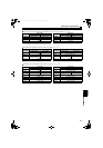
2)Remote register (For the details, refer to page 113.)
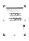
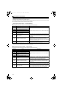
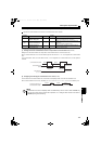
I/O signals when one station (FR-A5NC compatible) in the CC-Link Ver.1 is occupied. (Pr. 544 = "0")
("n" indicates a value determined by the station number setting.)
The upper 8 bits are always H00 even if a value other than H00 is set.
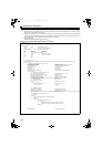
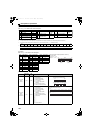
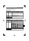
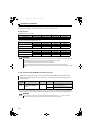
I/O signals when one station in the CC-Link Ver.1 is occupied. (Pr. 544 = "1")
("n" indicates a value determined by the station number setting.)
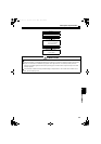
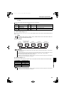
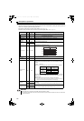
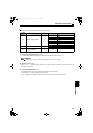
I/O signals when the double setting is set in the CC-Link Ver.2 (Pr. 544 = "12")
("n" indicates a value determined by the station number setting. )
Device No.
Description
Device No.
Description
Upper 8 Bits Lower 8 Bits Upper 8 Bits Lower 8 Bits
RWwn Monitor code 2 Monitor code 1 RWrn First monitor value
RWwn+1 Not used RWrn+1 Second monitor value
RWwn+2 H00(arbitrary)
Instruction Code RWrn+2 Reply code
RWwn+3 Write data RWrn+3 Read data
Device No.
Description
Device No.
Description
Upper 8 Bits Lower 8 Bits Upper 8 Bits Lower 8 Bits
RWwn
Monitor code 2 Monitor code 1
RWrn
First monitor value
RWwn+1
Not used
RWrn+1
Second monitor value
RWwn+2
Link parameter
extended setting
Instruction code
RWrn+2
Reply code H00
RWwn+3
Write data
RWrn+3
Read data
Device No.
Description
Device No.
Description
Upper 8 Bits Lower 8 Bits Upper 8 Bits Lower 8 Bits
RWwn Monitor code 2 Monitor code 1 RWrn First monitor value
RWwn+1 Not used RWrn+1 Second monitor value
RWwn+2
Link parameter
extended setting
Instruction code RWrn+2 Reply code H00
RWwn+3 Write data RWrn+3 Read data
RWwn+4 Monitor code 3 RWrn+4 Third monitor value
RWwn+5 Monitor code 4 RWrn+5 Fourth monitor value
RWwn+6 Monitor code 5 RWrn+6 Fifth monitor value
RWwn+7 Monitor code 6 RWrn+7 Sixth monitor value
HC2.book 111 ページ 2012年11月19日 月曜日 午前10時52分