


9
1
OUTLINE
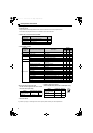
Precautions for selecting peripheral devices
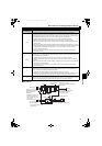
EMC measures
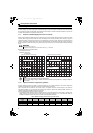
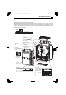
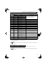
Noise
Transmission Path
Measures
1) 2) 3)
When the devices, which handle low-level signals and are susceptible to noises (such as measuring
instruments, receivers and sensors), are installed near or in the same enclosure with the converter, or their
signal cables are placed near of in the same enclosure with the converter, the devices may malfunction due to
air-propagated electromagnetic noises. In that cases, following measures must be taken.
(1) Install the easily affected devices as far away from the converter and inverter as possible.
(2) Place the easily affected signal cables as far away from the converter and inverter as possible.
(3) Do not place the signal cables and power cables (converter I/O cables) in parallel with each other and do
not bundle them.
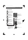
(4)Insert line noise filters ( FR-BLF, RC5128 (available product manufactured by Soshin Electric Co., Ltd.)) and
radio noise filters (FR-BIF) into the input side of the converter, and insert line noise filters (FR-BLF, RC5128
(available product manufactured by Soshin Electric Co., Ltd.)) into the output side of the inverter to
suppress cable-radiated noises.
(5) Use shield cables for signal cables and power cables and place them in individual metal conduits to
produce further effects.
4) 5) 6)
When the signal cables are placed in parallel with or bundled with the power cables, magnetic and static
induction noises may be transmitted to the signal cables which causes the devices to malfunction. In that case,
the following measures must be taken.
(1) Install the easily affected devices as far away from the converter and inverter as possible.
(2) Place the easily affected signal cables as far away from the converter, inverter, and their I/O cables as
possible.
(3) Do not place the signal cables and power cables ( I/O cables of the converter and inverter) in parallel with
each other and do not bundle them.
(4) Use shield cables for signal cables and power cables and place them in individual metal conduits to
produce further effects.
7)
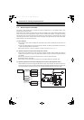
When the peripheral devices are connected to the same power supply line with the converter, converter-
generated noises may flow back through the power supply cable to the devices, causing malfunction of the
devices. In that case, the following measures must be taken.
(1) Install radio noise filters (FR-BIF) to the power cable (input cable) of the converter.
(2) Install the line noise filters (FR-BLF, RC5128 (available product manufactured by Soshin Electric Co., Ltd.))
to the power cable (input cable) of the converter and to the power cable (output cable) of the inverter.
8)
When a closed loop circuit is configured by connecting the wiring of a peripheral device to the converter,
leakage current may flow through the ground (earth) cable of the converter, causing malfunction of the device.
In that case, disconnecting the ground (earth) cable of the device may remove the malfunction.
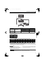
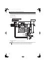
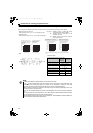
Sensor
Use 4-core cable for motor power
cable and use one cable as
earth (ground) cable.
Use a shielded twisted pair cable
Power supply
Control power supply
Do not earth (ground) shield
but connect it to signal common cable.
Enclosure
Decrease carrier
frequency
Motor
M
Install line noise filter
(FR-BLF, FR-BSF01) on the inverter
output side
Do not earth (ground)
enclosure directly
Do not earth (ground)
control cable
Separate the inverter and
power line by more than
30cm (at least 10cm) from
sensor circuit.
Power
supply
for sensor
FR-
BLF
FR-
BIF
FR-
BLF
Inverter
Converter
Reactor 2
Reactor 1
Outside box
Refer to page 53 for earthing
(grounding) the high power
factor converter and
accessories.
HC2.book 9 ページ 2012年11月19日 月曜日 午前10時52分