


149
Common specifications
6
SPECIFICATIONS
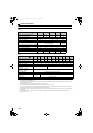
6.2 Common specifications
Can be displayed only on the operation panel (FR-DU07-CNV).
Can be displayed only on the option parameter unit (FR-PU07).
Temperature applicable for a short time, e.g. in transit.
This protective function is not available in the initial status.
This protective function is enabled when FR-A7NC is mounted.
2.9m/s
2
or less for the 160K or higher.
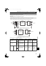
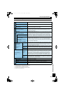
Control specification
Control method
PWM control
Power supply frequency range
50Hz to 60Hz
Current limit level
Current limit value selectable (0 to 220% variable)
Operation specification
Input signal (Five terminal)
The following signals can be assigned to Pr. 3 to Pr. 7 (input terminal function selection):
converter stop, monitor switching, converter reset, external thermal relay, and inrush
resistance overheat detection.
Output signal
Open collector output (Five terminals)
Relay output (One terminal)
The following signals can be assigned to Pr. 11 to Pr. 16 (output terminal function selection):
inverter run enable signal, converter reset, converter running, overload alarm, power
supply phase detection, output voltage match, instantaneous power failure detection,
regenerative drive recognition, electronic thermal relay pre-alarm, fan alarm, heatsink
overheat pre-alarm, during retry, input current detection, zero current detection, life alarm,
maintenance timer, instantaneous power failure detection hold, alarm, and fault output.
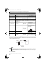
Operating status
For meter
Pulse train output
(Max. 2.4kHz: one terminal)
Analog output
(Max. 10VDC: one terminal)
The following signals can be assigned to Pr. 54 FM terminal function selection (pulse train
output) and Pr. 50 AM terminal function selection (analog output): power supply frequency,
input current, input voltage, converter output voltage, electronic thermal relay load factor,
input power, reference voltage output.
Indication
Operation panel
(FR-DU07
-CNV)
Parameter unit
(FR-PU07)
Operating
status
Power supply frequency, input current, input voltage, fault or alarm indication, converter
output voltage, electronic thermal relay load factor, cumulative energization time,
cumulative power, input power, input power (with regenerative display), I/O terminal
status
*1, power/regenerative drive indication
Fault record
Fault definition is displayed when a fault occurs. Past eight fault records and the data right
before the fault (input voltage/current/bus voltage/cumulative energization) are stored.
Interactive
guidance
Function (help) for operation guide
Protective/warning
function
Protective
function
Overcurrent, overvoltage, converter protection thermal, fin overheat, instantaneous power
failure, undervoltage, input phase loss, HC2 dedicated board disconnection, input power
supply fault, external thermal relay operation
, parameter error, PU disconnection ,
retry count excess
, converter CPU fault, operation panel power supply short circuit,
24VDC power output short circuit, input current detection value exceeded
, inrush
current limit circuit fault, internal circuit fault, option fault
, communication option fault .
Warning
functions
Fan alarm, overload signal detection, electronic thermal relay pre-alarm, PU stop,
maintenance timer alarm
, parameter write error, copy operation error, operation panel
lock, parameter copy alarm, no-phase detection
Environment
Surrounding air temperature
-10C to +50C (non-freezing)
Ambient humidity
90%RH or less (non-condensing)
Storage temperature
-20C to +65C
Atmosphere
Indoors (without corrosive gas, flammable gas, oil mist, dust and dirt etc.)
Altitude/ vibration
Maximum 1,000m above sea level, 5.9m/s
2
or less at 10 to 55Hz (directions of X, Y, Z
axes)
HC2.book 149 ページ 2012年11月19日 月曜日 午前10時52分