


127
4
PROTECTIVE FUNCTIONS
Causes and corrective actions
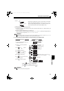
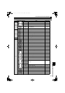
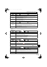
(2) Warning
When a warning occurs, The converter continues its operation.
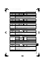
Operation Panel
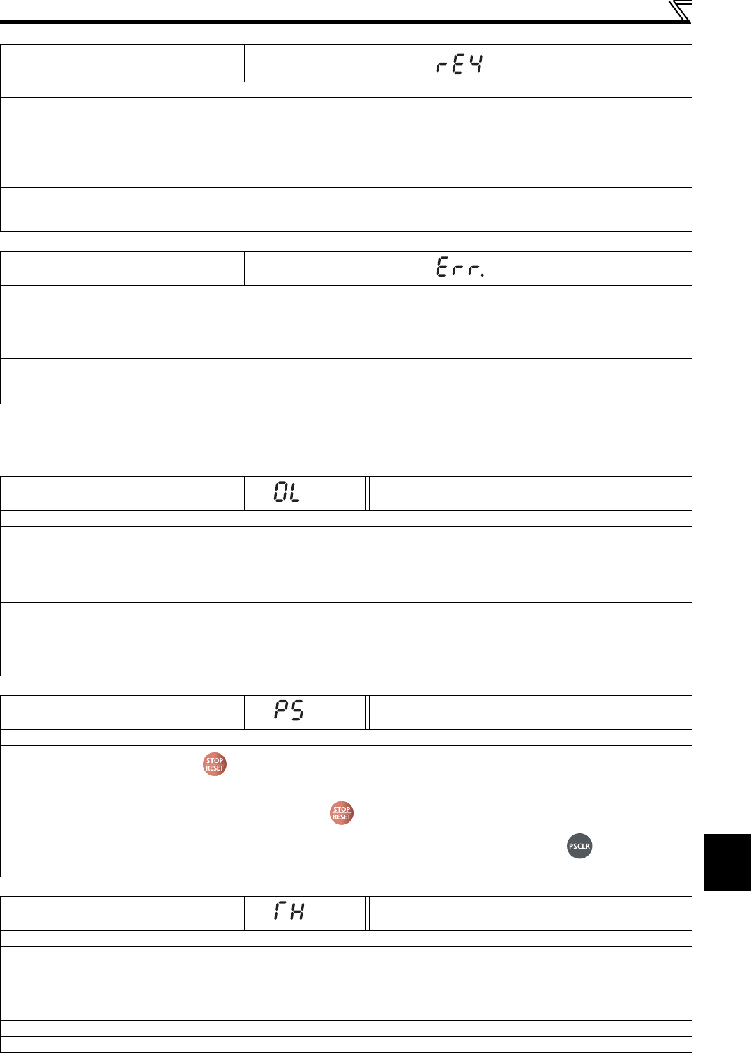
Indication
rE4
Name
Model error
Description
Parameter write or parameter verification of the parameter copy function is performed to an invalid model.
When writing of copied parameters is attempted after reading of copied parameters is interrupted
Checkpoint
Check that the verifying converter is the same model.
Check that the reading of copied parameter is not interrupted by switching OFF the power or by
disconnecting the operation panel.
Check if parameter copy writing is attempted while Pr. 77 Parameter write selection = "1".
Corrective action
Perform parameter copy and parameter verification to the same model (FR-HC2 series).
Read the copied parameter again.
Perform parameter copy writing by setting Pr. 77 Parameter write selection = "2".
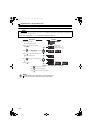
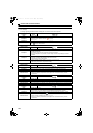
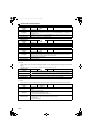
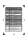
Operation Panel
Indication
Err.
Description
When RES signal is ON.
When the PU and the converter cannot make normal communication. (Contact faults of the connector)
This error may occur when the voltage at the input side of the converter drops.
When using a separate power source for the control circuit power (R1/L11, S1/L21) from the main circuit
power (R/L1, S/L2, T/L3), this error may appear at turning ON of the main circuit. It is not a fault.
Corrective action
Turn OFF the RES signal.
Check the connection between the PU and the converter.
Check the voltage on the input side of the converter.
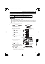
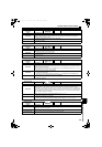
Operation Panel
Indication
OL
FR-PU07 OL
Name
Overload signal detection
Description
Appears when the current limit function of the converter activates.
Checkpoint
Check if the acceleration/deceleration time of the inverter is too short.
Check that the load is not too heavy.
Are there any failure in peripheral devices?
Check that the Pr. 22 Current limit level setting is appropriate. (Refer to page 79)
Corrective action
Set the acceleration/deceleration time of the inverter longer.
Reduce the load weight.
Check that the peripheral devices are operating properly.
Current limit level of the output current can be set with Pr. 22 Current limit level. (Initial setting is 150%.) Set
the current limit level higher with Pr. 22 Current limit level.
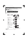
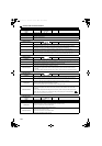
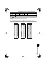
Operation Panel
Indication
PS
FR-PU07 PS
Name
PU stop
Description
Stop with of the PU is set in Pr. 75 Reset selection/disconnected PU detection/PU stop selection. (For Pr. 75,
refer to page 92.)
Checkpoint
Check for a stop made by pressing of the operation panel.
Corrective action
Turn the converter stop signal (SOF) ON to stop the converter operation, and press to release the PU
stop.
Operation Panel
Indication
TH
FR-PU07 TH
Name
Electronic thermal relay pre-alarm
Description
Appears if the cumulative value of the electronic thermal relay reaches or exceeds 85% of the preset level.
If it reaches 100% of the preset level, converter overload trip (E. THT) occurs.
THP signal can be simultaneously output with the [TH] display. For the terminal used for THP signal, set "8
(positive logic)" or "108 (negative logic)" to any of Pr. 11 to Pr. 16 (output terminal function selection). (Refer to
page 78)
Checkpoint
Check for large load or sudden acceleration.
Corrective action
Reduce the load and frequency of operation.
HC2.book 127 ページ 2012年11月19日 月曜日 午前10時52分