


71
3
PARAMETERS
Parameter unit (FR-PU07), parameter unit with battery pack (FR-PU07BB(-L))
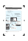
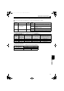
3.2.4 Function menu
Press in any operation mode to call the function menu, on which you can perform various functions.
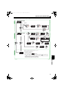
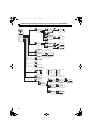
(1) Function menu list
(2) Function menu transition
REMARKS
Some menus are not available.
Function menu Description
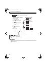
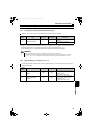
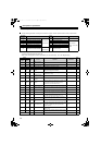
1. MONITOR The monitor list appears, and you can change from one monitor to another and set the first priority monitor.
2. PU Oper This menu is displayed but its function is disabled.
3. Pr. List The parameter menu appears, and you can perform "parameter setting" and "parameter change list display".
4. Pr. Clear The parameter clear menu appears, and you can perform "parameter clear" and "all clear".
5. Alarm Hist This function displays history of past eight faults (alarms).
6. AlarmClear This function clears all the fault (alarm) history.
7. Inv.Reset This function resets the converter. (Also resets the inverter at the same time.)
8. T/Shooting This menu is displayed but its function is disabled.
9. S/W This function displays the firmware control number of the converter.
10. Selectop This menu is displayed but its function is disabled.
11. Option This function displays the option fitting states of the option connectors 1 and 2.
12. FRCpy set The function can perform the "parameter copy" (read, write, verification).
Bus voltage [V]
Fault description ∗ The latest 8 faults are displayed
Power supply frequency[Hz]
Electronic thermal relay load factor [%]
Input power [kW]
Cumulative power [kW]
Cumulative energization time [hr]
Nothing is displayed.
Nothing is displayed.
Nothing is displayed.
Nothing is displayed.
Nothing is displayed.
Output signal
∗2
3
4
5
6
7
8
9
10
11
12
3 Dc Bus
4 Alarm His
5 Hz In
6 THT %
7 Pwr In
8 Cum Pwr
9 Cum Opr
10
11
12
13
14
15 I/P Signal
16 O/P Signal
2 PU Oper
1 MONITOR
Input signal ∗1
Does not function.
Input current [A]
1 Current
Input voltage [V]
2 Voltage
STF
STR
AU
RT
RL
RM
RH
JOG
MRS
STOP
RES
CS
RL
RM
RH
MRS
RES
RUN
SU
IPF
OL
FU
ABC1
ABC2
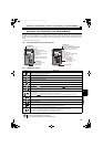
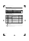
Input signal monitor
The displayed names correspond with the
terminals as shown below.
The displayed names correspond with the
terminals as shown below.
The displayed names other than
above do not have any functions
∗1
∗2 Output signal monitor
Terminal X1
Terminal X2
Terminal ROH
Terminal SOF
Terminal RES
Terminal RSO
Terminal CVO
Terminal Y1
Terminal Y2
Terminal Y3
Terminal RDY
Terminal ABC
RUN
SU
IPF
OL
FU
ABC1
ABC2
HC2.book 71 ページ 2012年11月19日 月曜日 午前10時52分