


110
Description of parameters
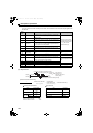
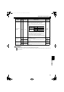
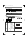
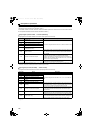
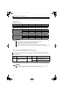
(3) CC-Link extended setting (Pr. 544)
The functions of the remote register can be extended. Refer to page 110 for the details of the remote I/O signals and the
remote registers.
The program used for the conventional inverter series (FR-A5NC) can be used.
The upper 8 bits of RWw2 are not used for the link parameter extended setting.
When using the double setting of the CC-Link Ver.2, station data of the master station must be set to double.
(If the master station is CC-Link Ver.1, this setting is not available. )
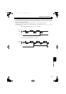
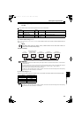
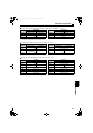
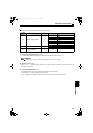
(4) I/O signal list
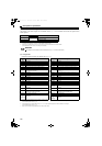
1)Remote I/O signals (32 points) (For details, refer to page 112.)
("n" indicates a value determined by the station number setting. )
These signals are set in the initial setting. Using Pr. 3 to Pr. 7, input signals assigned to the device numbers can be changed.
For the available signals, refer to page 76.
These signals are set in the initial setting. Using Pr. 11 to Pr. 16, output signals assigned to the device numbers can be changed.
For the available signals, refer to page 78.
Output of the error status flag signal depends on the retry function setting.
Pr. 544 Setting Description
CC-Link Ver.
0 (Initial setting)
1
Occupies one station (FR-A5NC compatible)
1 Occupies one station
12
2 Occupies one station, double setting
REMARKS
The setting becomes valid after converter reset. (Refer to page 124 for the converter reset.)
Device
No.
Signal Device No. Signal
RYn0 Not used RXn0 Not used
RYn1 Not used RXn1 Not used
RYn2 Converter stop (terminal SOF function)
RXn2 Converter ready (inverter run enable signal)
RYn3 Monitor switching (terminal X1 function)
RXn3 Converter reset(terminal RSO function)
RYn4 Monitor switching (terminal X2 function) RXn4 During converter run(terminal CVO function)
RYn5
Converter reset (
terminal
RES
function
)
RXn5 Overload alarm(terminal Y1 function)
RYn6
ROH inrush resistance overheat detection
(terminal ROH function)
RXn6
Power supply phase detection(terminal Y2
function)
RYn7 Not used RXn7 Output voltage match (terminal Y3 function)
RYn8 Not used RXn8 Fault(terminal ABC function)
RYn9 Not used RXn9 Not used
RYnA Not used RXnA Not used
RYnB Not used RXnB Not used
RYnC Monitor command RXnC Monitoring
RYnD Not used RXnD Not used
RYnE Not used RXnE Not used
RYnF Instruction code execution request RXnF Instruction code execution completion
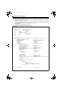
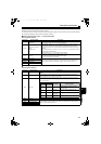
RY(n+1)0 to
RY(n+1)7
Reserved
RX(n+1)0 to
RX(n+1)7
Reserved
RY(n+1)8
Not used
(initial data process completion flag)
RX(n+1)8
Not used
(initial data process request flag)
RY(n+1)9
Not used
(initial data process request flag)
RX(n+1)9
Not used
(initial data process completion flag)
RY(n+1)A
Error reset request flag
RX(n+1)A
Error status flag
RY(n+1)B
to
RY(n+1)F
Reserved
RX(n+1)B
Remote station ready
RX(n+1)C
to
RX(n+1)F
Reserved
HC2.book 110 ページ 2012年11月19日 月曜日 午前10時52分