


II
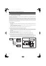
2.9.1 Connection diagram (when using with the FR-A700 series)......................................................... 47
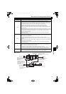
2.9.2 Wiring of main circuit .................................................................................................................... 48
2.10 Notes on earthing (grounding).......................................................... 53
2.11 Compatible inverter for the high power factor converter................ 54
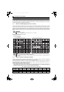
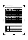
2.11.1 Applicable inverter capacity .......................................................................................................... 54
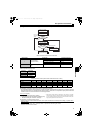
2.11.2 Inverter parameter settings........................................................................................................... 55
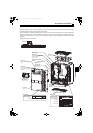
2.12 Wiring of several inverters to one converter ................................... 56
2.13 Wiring of control circuit .................................................................... 58
2.13.1 Description of control circuit terminal............................................................................................ 58
2.13.2 Changing the control logic ............................................................................................................ 60
2.13.3 Control circuit terminal layout ....................................................................................................... 62
2.13.4 Wiring instructions ........................................................................................................................ 63
2.13.5 When connecting the operation panel or parameter unit using a connection cable ..................... 64
2.13.6 Communication operation (computer link operation) .................................................................... 64
3 PARAMETERS 65
3.1 Operation panel (FR-DU07-CNV) ....................................................... 66
3.1.1 Names and functions of the operation panel (FR-DU07-CNV)..................................................... 66
3.1.2 Basic operation (factory setting) ................................................................................................... 67
3.1.3 Changing the parameter setting value.......................................................................................... 68
3.2 Parameter unit (FR-PU07),
parameter unit with battery pack (FR-PU07BB(-L)) ......................... 69
3.2.1 Parts identification of the parameter unit ...................................................................................... 69
3.2.2 Explanation of keys....................................................................................................................... 69
3.2.3 Monitoring function ....................................................................................................................... 70
3.2.4 Function menu .............................................................................................................................. 71
3.3 Parameter list ................................................................................... 73
3.4 Description of parameters ................................................................ 75
3.4.1 Displaying and hiding extended parameters (Pr. 0)..................................................................... 75
3.4.2 Input frequency to converter (Pr. 1, Pr. 2) ................................................................................... 75
3.4.3 Input terminal function selection (Pr. 3 to Pr. 7)........................................................................... 76
3.4.4 Operation selection of SOF signal and OH signal (Pr. 8, Pr. 9)................................................... 77
3.4.5 Output terminal function selection (Pr. 10 to Pr. 16).................................................................... 78
3.4.6 DC voltage control (Pr. 22 to Pr. 24, Pr. 80, Pr. 81) .................................................................... 79
3.4.7 Input current detection function (Y12 signal, Y13 signal, Pr. 25 to Pr. 30) .................................. 80
3.4.8 Displaying the life of the converter parts (Pr. 31 to Pr. 33) .......................................................... 81
3.4.9 Maintenance timer alarm (Pr. 34, Pr. 35)..................................................................................... 82
3.4.10 Cooling fan operation selection (Pr. 36) ...................................................................................... 83
3.4.11 Instantaneous power failure detection hold (Pr. 44) .................................................................... 83
3.4.12 Reference of the terminal FM (pulse train output) and terminal AM (analog output) (Pr. 45, Pr. 49,
Pr. 51, Pr. 53, Pr. 55, Pr. 56) ....................................................................................................... 84
HC2.book II ページ 2012年11月19日 月曜日 午前10時52分