


35
2
INSTALLATION AND WIRING
Wiring of main circuit (FR-HC2-7.5K to 75K, FR-HC2-H7.5K to H220K)
2.7.2 Wiring of main circuit
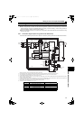
(1) Wiring of power supply and reactor 1
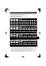
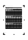
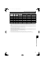
• Cable size differs by capacity. Select an appropriate cable by referring to 2.6.3 Cable sizes of the main control circuit terminals
and earth (ground) terminals (refer to page 31) and perform wiring.
NOTE
• When connecting the converter to the inverter, match the control logic (sink logic (initial setting)/source logic). The
converter does not operate properly if the control logic is different.
(Refer to page 60 for the switching of the control logic. Refer to the Instruction Manual of the inverter for the switching
of the control logic of the inverter.)
• Keep the wiring length between terminals as short as possible.
• When sudden large distortion or depression of power supply occurs, reactor may generate abnormal acoustic noise.
This acoustic noise is caused by the power supply fault and not by the damage of the converter.
• Do not connect the DC reactor to the inverter when using a high power factor converter.
• When using a sine wave filter with FR-HC2 (75K or higher), select MT-BSL-HC as a reactor for the sine wave filter.
CAUTION
Check the connection order of the reactor 1 and the reactor 2. Incorrect connection may damage the
converter and reactors.
Always connect the terminal RDY of the converter to the terminal MRS or the inverter terminal of which X10
signal is assigned to. Also, always connect the terminal SE of the converter to the terminal SD of the
inverter. If these are not connected, the converter may be damaged.
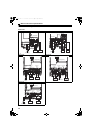
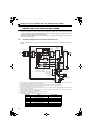
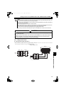
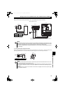
<Wiring example of 7.5K>
The terminal arrangement differs by capacity. Check the terminal arrangement on 6.3
Outline dimensions (refer to page 150).
MCCB
MC
Reactor 1
R/L1
S/L2
T/L3
R2/L12
S2/L22
T2/L32
Power
supply
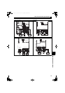
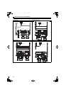
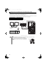
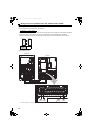
MCCB
MC
Reactor 1
Power
supply
R/L1
S/L2
T/L3
R2/
L12
S2/
L22
T2/
L32
HC2.book 35 ページ 2012年11月19日 月曜日 午前10時52分