


80
Description of parameters
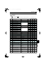
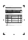
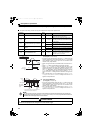
3.4.7 Input current detection function (Y12 signal, Y13 signal, Pr. 25 to Pr. 30)
The input current during converter running can be detected and output to the output terminal.
Parameter
Number
Name
Initial
Value
Setting Range Description
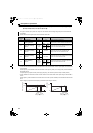
25 Input current detection level 150% 0 to 220%
Set the input current detection level.
100% is the rated converter current.
26
Input current detection signal delay
time
0s 0 to 10s
Set the input current detection period. Set the
time from when the input current has risen above
the setting until the input current detection signal
(Y12) is output.
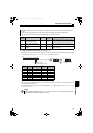
27
Input current detection signal retention
time
0.1s
0 to 10s Set the retention time when Y12 signal is ON.
9999
Y12 signal ON status is retained. The signal is
turned OFF at the next start.
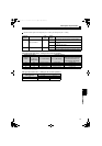
28
Input current detection operation
selection
0
0 Operation continues when Y12 signal is ON.
1 Converter trips when Y12 signal is ON. (E.CDO)
29 Zero current detection level 5% 0 to 220%
Set the zero current detection level.
The rated converter current is regarded as 100%.
30 Zero current detection time 0.5s 0 to 1s
Set the period from when the input current drops
below the Pr. 29 value until the zero current
detection signal (Y13) is output.
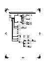
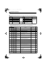
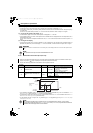
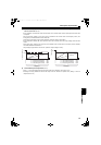
(1) Input current detection
(Y12 signal, Pr. 25 to Pr. 28 )
If the input current remains higher than the Pr. 25 setting during the
converter operation for longer than the time set in Pr. 26, the output
current detection signal (Y12) is output from the converter's open
collector or relay output terminal.
When Y12 signal turns ON, the ON state is held for the time set in Pr.
27.
When Pr. 27 = "9999", the ON state is held until the next start.
When Pr. 28 = "1", turning Y12 signal ON stops the output of the
converter and displays the input current detection alarm (E.CDO).
When the trip occurs, Y12 signal stays ON for the time set in Pr. 27
with Pr. 27 9999 setting, and Y12 signal stays ON until a reset with
Pr. 27 = 9999 setting. E.CDO does not occur by setting Pr. 28 = "1"
while Y12 is ON. Pr. 28 setting becomes valid after Y12 signal turns
OFF.
Set "12 (positive logic)" or "112 (negative logic)" to any of Pr. 11 to Pr.
16 (output terminal function selection) to assign the function of Y12
signal to the output terminal.
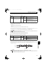
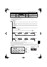
(2) Zero current detection
(Y13 signal, Pr. 29, Pr. 30 )
If the input current remains lower than the Pr. 29 setting during the
converter operation for longer than the time set in Pr. 30, the zero
current detection signal (Y13) is output from the converter's open
collector or relay output terminal.
Set "13 (positive logic)" or "113 (negative logic)" to any of Pr. 11 to Pr.
16 (output terminal function selection) to assign the function of Y13
signal to the output terminal.
NOTE
The response time of Y12 and Y13 signals is approximately 0.1s. Note that the response time varies with the load.
Changing the terminal assignment using Pr. 11 to Pr. 16 (output terminal function selection) may affect other functions. Set
parameters after confirming the function of each terminal.
CAUTION
A safety backup such as an emergency brake must be provided to prevent hazardous condition to the
machine and equipment when using the zero current detection signal.
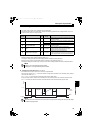
Time
Pr. 25
OFF
ON
OFF
Input current
detection signal
(Y12)
Pr. 27
Minimum 0.1s
(initial value)
Input current
Pr. 27
9999, Pr. 28 = 0
Pr. 26
OFF ON
Start signal
Time
p
current
OFF
ON
Zero current
detection time
(Y13)
Pr. 30
Detection
time
Pr. 30
Detection
time
Pr. 29
OFF
ON
0[A]
0.1s ∗
Pr. 29
Once turned ON, the zero current detection time
signal (Y13) is held on for at least 0.1s.
∗
HC2.book 80 ページ 2012年11月19日 月曜日 午前10時52分