


82
Description of parameters
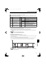
(2) Life display of the inrush current limit circuit (Pr. 32)
The life of the inrush current limit circuit (relay, contactor and inrush resistor) is displayed in Pr. 32.
The number of contact (relay, contactor, thyristor) ON times is counted, and it is counted down from 100% (0 time) every
1%/1,000 times.
As soon as 10% (90,000 times) is reached, Pr. 31 bit 3 is turned ON, and also an alarm is output to Y14 signal.
(3) Control circuit capacitor life display (Pr. 33)
The deterioration degree of the control circuit capacitor is displayed in Pr. 33 as a life.
In the operating status, the control circuit capacitor life is calculated from the energization time and temperature, and is
counted down from 100%.
As soon as the control circuit capacitor life falls below 10%, Pr. 31 bit 0 is turned ON, and also an alarm is output to Y14
signal.
(4) Cooling fan life display
The cooling fan speed of 50% or less is detected and "FN" is displayed on the operation panel (FR-DU07-CNV) and
parameter unit (FR-PU07). As an alarm display, Pr. 31 bit 2 is turned ON, and also an alarm is output to the Y14 signal.
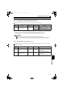
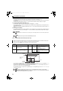
3.4.9 Maintenance timer alarm (Pr. 34, Pr. 35)
The cumulative energization time of the converter is stored into the EEPROM every hour and indicated in Pr. 34
Maintenance timer in 100h increments. Pr. 34 is clamped at 9998 (999800h).
The maintenance timer alarm output signal (Y15) is output when the time set in Pr. 34 has reached the time set in Pr. 35
Maintenance timer alarm output set time (100h increments).
For the terminal used for Y15 signal, set "15 (positive logic)" or "115 (negative logic)" to any of Pr. 11 to Pr. 16 (output
terminal function selection).
REMARKS
When the converter is mounted with two or more cooling fans, "FN" is displayed with one or more fans with speed of 50% or
less.
NOTE
For replacement of each part, contact the nearest Mitsubishi FA center.
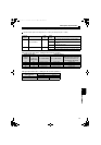
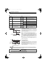
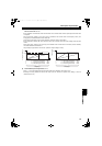
When the cumulative energization time of the converter reaches the parameter set time, the maintenance timer output
signal (Y15) is output. (MT) is displayed on the operation panel (FR-DU07-CNV).
This can be used as a guideline for the maintenance time of peripheral devices.
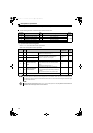
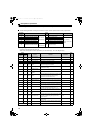
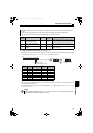
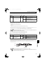
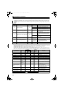
Parameter
Number
Name Initial Value Setting Range Description
34 Maintenance timer 0 0(1 to 9998)
Displays the cumulative energization time of
the converter in 100h increments.
Reading only
Writing the setting of "0" clears the
cumulative energization time.
35
Maintenance timer alarm output set
time
9999
0 to 9998
Set the time taken until when the
maintenance timer alarm output signal (Y15)
is output.
9999 No function
NOTE
The cumulative energization time is counted every hour. The energization time of less than 1h is not counted.
Changing the terminal assignment using Pr. 11 to Pr. 16 (output terminal function selection) may affect other functions. Set
parameters after confirming the function of each terminal.
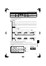
First power
Time
ON
Maintenance
timer
(Pr. 34)
Set "0" in Pr. 34
Y15 signal
MT display
OFF ONON
Pr. 35
9998
(999800h)
HC2.book 82 ページ 2012年11月19日 月曜日 午前10時52分