


78
Description of parameters
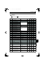
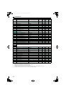
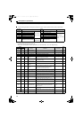
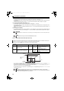
3.4.5 Output terminal function selection (Pr. 10 to Pr. 16)
(1) Output signal list
Functions of the output terminals can be set.
Refer to the following table and set the parameters. (0 to 99: Positive logic, 100 to 199: Negative logic)
Use the following parameters to change the functions of the open collector output terminals and relay output terminal.
Parameter
Number
Name
Initial
Value
Initial Signal Setting Range
10 RDY signal logic selection
Open collector
output terminal
100 RDY (Inverter run enable signal) 0, 100
11 RSO terminal function selection 1 RSO (converter reset)
0 to 16, 98, 99,
100 to 116, 198, 199,
9999
12 CVO terminal function selection 2 CVO (converter running)
13 Y1 terminal function selection 3 OL (overload alarm)
14 Y2 terminal function selection 4 PHS (power supply phase detection)
15 Y3 terminal function selection 5 Y5 (output voltage match)
16 ABC terminal function selection
Relay
output terminal
99 ALM (fault output)
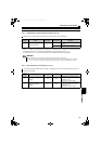
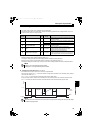
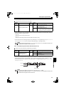
Setting
Signal
Name
Function Operation
Related
Parameters
Refer
to
page
Positive
Logic
Negative
Logic
0 100 RDY
Inverter run enable
signal
Output when inverter can run.
1 101 RSO Converter reset Output during a converter reset.
2 102 CVO During converter run
Output when the converter is running.
3 103 OL Overload alarm Output when the current limit function is active. Pr. 22, Pr. 23, Pr. 24 79
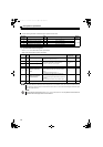
4104PHS
Power supply phase
detection
Output when a phase is confirmed after a completion
of the power supply phase detection.
5 105 Y5 Output voltage match
Output when the detected bus voltage equals to the
commanded bus voltage.
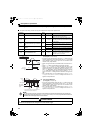
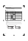
6106IPF
Instantaneous power
failure
Output when an instantaneous power failure is detected. Pr. 57 89
7107Y7
Regenerative drive
recognition
Output at regenerative operation.
8108THP
Electronic thermal relay
pre-alarm
Output when the electronic thermal relay cumulative value
reaches 85% of the transistor protection thermal activation
level. (Electronic thermal relay protection (E.THT)
activates when the value reaches 100%.)
9 109 FAN Fan fault output Output at the time of a fan fault. Pr. 36 83
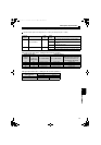
10 110 FIN
Heatsink overheat pre-
alarm
Output when the heatsink temperature reaches about 85%
of the heatsink overheat protection providing temperature.
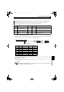
11 111 RTY During retry Output during retry processing.
Pr. 65, Pr. 67 to Pr. 69
91
12 112 Y12 Input current detection
Output when the converter's input current is higher than
the Pr. 25 setting for longer than the time set in Pr. 26.
Pr. 25, Pr. 26 80
13 113 Y13 Zero current detection
Output when the converter's input current is lower than the
Pr. 29 setting for longer than the time set in Pr. 30.
Pr. 29, Pr. 30 80
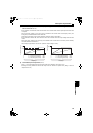
14 114 Y14 Life alarm
Output when the control circuit capacitor or the inrush
current limit circuit approaches the end of its service life.
Pr. 31 to Pr. 33 81
15 115 Y15
Maintenance timer
signal
Output when Pr. 34 rises to or above the Pr. 35 setting. Pr. 34, Pr. 35 82
16 116 Y16
Instantaneous power
failure detection hold
This signal is output when the IPF signal turns ON. Output
of this signal is held until a reset or Pr. 44 = "0" is set.
This signal is available during the high power factor
converter operation.
Pr. 44 83
98 198 LF Alarm output
Output when an alarm (fan failure or communication error
warning) occurs.
Pr. 36, Pr. 121 83, 98
99 199 ALM Fault output
Output when the converter's protective function activates
to stop the output (at fault occurrence).
9999
No function
HC2.book 78 ページ 2012年11月19日 月曜日 午前10時52分