


188
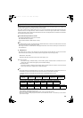
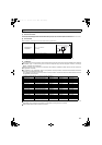
These instruction codes are used to write or read parameters through the RS-485 communication and the CC-Link communication.
(Refer to page 98 for the RS-485 communication. Refer to page 109 for the CC-Link communication.)
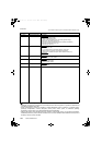
"" indicates valid and "" indicates invalid of "parameter copy", "parameter clear", and "all parameter clear".
These parameters are not cleared by the parameter clear (all parameter clear) command, which are sent through RS-485 communication and CC-Link
communication. (Refer to page 98 for the RS-485 communication. Refer to page 109 for the CC-Link communication.)
Read and write of this parameter is enabled only when communicating through the PU connector.
Symbols in the table indicate parameters that function when the option is mounted.
...... FR-A7NC
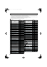
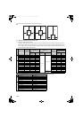
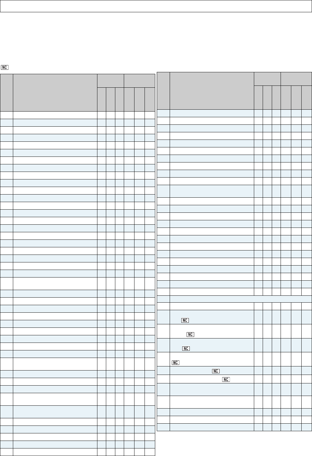
Appendix 1 Instruction code list
Pr. Name
Instruction
Code
Parameter
Read
Write
Extended
Copy
Clear
All clear
0 Simple mode selection 00 80 0
1 Maximum power supply frequency 01 81 0
2 Minimum power supply frequency 02 82 0
3 ROH terminal function selection 03 83 0
4 SOF terminal function selection 04 84 0
5 X1 terminal function selection 05 85 0
6 X2 terminal function selection 06 86 0
7 RES terminal function selection 07 87 0
8 SOF input selection 08 88 0
9 OH input selection 09 89 0
10 RDY signal logic selection 0A 8A 0
11 RSO terminal function selection 0B 8B 0
12 CVO terminal function selection 0C 8C 0
13 Y1 terminal function selection 0D 8D 0
14 Y2 terminal function selection 0E 8E 0
15 Y3 terminal function selection 0F 8F 0
16 ABC terminal function selection 10 90 0
22 Current limit level 16 96 0
23 Current limit level (regenerative) 17 97 0
24 OL signal output timer 18 98 0
25 Input current detection level 19 99 0
26 Input current detection signal delay time 1A 9A 0
27
Input current detection signal retention
time
1B 9B 0
28 Input current detection operation selection 1C 9C 0
29 Zero current detection level 1D 9D 0
30 Zero current detection time 1E 9E 0
31 Life alarm status display 1F 9F 0
32 Inrush current limit circuit life display 20 A0 0
33 Control circuit capacitor life display 21 A1 0
34 Maintenance timer 22 A2 0
35 Maintenance timer alarm output set time 23 A3 0
36 Cooling fan operation selection 24 A4 0
44
Instantaneous power failure detection
signal clear
2C AC 0
45 AM output filter 2D AD 0
46 Watt-hour meter clear 2E AE 0
47 Energization time carrying-over times 2F AF 0
48
Cumulative power monitor digit shifted
times
30 B0 0
49
Power supply frequency monitoring
reference
31 B1 0
50 AM terminal function selection 32 B2 0
51 Input power monitoring reference 33 B3 0
52 DU/PU main display data selection 34 B4 0
53 Input voltage monitoring reference 35 B5 0
54 FM terminal function selection 36 B6 0
55 Bus voltage monitoring reference 37 B7 0
56 Current monitoring reference 38 B8 0
57 Restart selection 39 B9 0
58 Free parameter 1 3A BA 0
59 Free parameter 2 3B BB 0
61 Key lock operation selection 3D BD 0
65 Retry selection 41 C1 0
67 Number of retries at fault occurrence 43 C3 0
68 Retry waiting time 44 C4 0
69 Retry count display erase 45 C5 0
75
Reset selection/disconnected PU
detection/PU stop selection
4B CB 0
77 Parameter write selection 4D CD 0
80 Voltage control proportional gain 50 D0 0
81 Voltage control integral gain 51 D1 0
82 Current control proportional gain 52 D2 0
83 Current control integral gain 53 D3 0
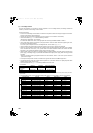
117 PU communication station number 11 91 1
118 PU communication speed 12 92 1
119 PU communication stop bit length 13 93 1
120 PU communication parity check 14 94 1
121 Number of PU communication retries 15 95 1
123 PU communication waiting time setting 17 97 1
124 PU communication CR/LF selection 18 98 1
145 PU display language selection 2D AD 1
269 Parameter for manufacturer setting. Do not set.
342 Communication EEPROM write selection 2A AA 3
500
Communication error execution waiting
time
00 80 5
501
Communication error occurrence count
display
01 81 5
502
Stop mode selection at communication
error
02 82 5
542
Communication station number (CC-Link)
2A AA 5
543
Baud rate (CC-Link)
2B AB 5
544
CC-Link extended setting
2C AC 5
C0
(900)
FM terminal calibration 5C DC 1
C1
(901)
AM terminal calibration 5D DD 1
989 Parameter copy alarm release 59 D9 9
990 PU buzzer control 5A DA 9
991 PU contrast adjustment 5B DB 9
Pr. Name
Instruction
Code
Parameter
Read
Write
Extended
Copy
Clear
All clear
HC2.book 188 ページ 2012年11月19日 月曜日 午前10時52分