


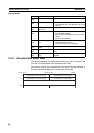

88
Allocated DM Area Words Section 3-3
Ranges
Areas and Word Ranges
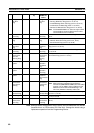
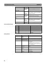
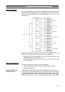
3-3-7 Slave User-set Allocations Reference Table
The slave block settings can be accessed in the Slave User-set Allocations
Reference Table. A maximum of two OUT and two IN areas (OUT 1, IN 1,
OUT 2, and IN 2) can be used for slave communications and their area and
size can be accessed in the table.
The OUT 1 and IN 1 areas and sizes are valid even if a Configurator is not
being used.
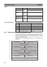
Name Range Details
OUT block 1/2 area See Areas
and Word
Ranges.
Shows the area.
First word in OUT
block 1/2
Shows the first word for the block.
No. of bytes in OUT
block 1/2
0000 to
03E8 Hex
(0 to 1,000
bytes)
Shows the block size in bytes. The OUT block
has not been allocated if this is set at 00 Hex.
IN block 1/2 area See Areas
and Word
Ranges.
Shows the area.
First word in IN
block 1/2
Shows the first word for the block.
No. of bytes in IN
block 1/2
0000 to
03E8 Hex
(0 to 1,000
bytes)
Shows the block size in bytes. The OUT block
has not been allocated if this is set at 00 Hex.
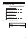
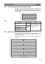
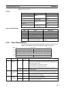
Code Name Word range
00 Hex --- The block is not used.
01 Hex CIO Area (CIO) 0000 to 17FF Hex (0 to 6143)
03 Hex Data Memory (DM) 0000 to 7FFF Hex (0 to 32767)
04 Hex Work Area (WR) 0000 to 01FF Hex (0 to 511)
05 Hex Holding Relay (HR) 0000 to 01FF Hex (0 to 511)
08 to 14
Hex
Expansion Data Memory (EM)
Bank 0 to bank C (13 banks)
0000 to 7FFF Hex (0 to 32767) for
all banks
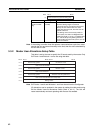
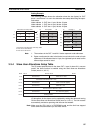
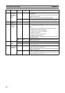
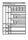
Word
Bit 15 Bit 08 Bit 07 Bit 00
Reserved by system
Slave OUT 1 area
m+31
First word in the slave OUT 1 area
m+32
OUT 1 area size (bytes)
m+33
Reserved by system
Slave IN 1 area
m+34
First word in slave IN 1
m+35
IN 1 area size (bytes)
m+36
Reserved by system
Slave OUT 2 area (Always 0)
m+37
First word in the slave OUT 2 area (Always 0)
m+38
OUT 2 area size (bytes) (Always 0)
m+39
Reserved by system
Slave IN 2 area
m+40
First word in slave IN 2
m+41
IN 2 area size (bytes)
m+42