


23
Specifications Section 1-3
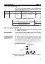
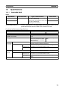
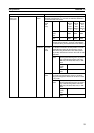
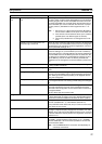
Remote I/O
master com-
munications
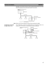
Slave allocation method Fixed allo-
cations
Select one of the following fixed allocation areas using the Fixed
Allocated Area Switches 1, 2, and 3 in the software switches in
the allocated CIO Area words.
Allocated
words
(CIO
Area)
I/O Size Fixed
Alloca-
tion
Area
Setting
1
Fixed
Alloca-
tion
Area
Setting
2
Fixed
Alloca-
tion
Area
Setting
3
Output
(OUT)
area
64 words 3200 to
3263
3400 to
3463
3600 to
3663
Input (IN)
area
64 words 3300 to
3363
3500 to
3563
3700 to
3763
Select one of the above areas using the software
switches. All are fixed at 1 word per node address.
The default setting is Fixed Allocation Area Setting 1.
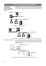
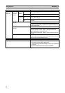
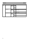
User-set
allocations
By allo-
cated DM
Area
words
Set the areas and the first words for the OUT 1 and
IN 1 blocks in the Scan List Setup Table in the allo-
cated DM Area words. Set the allocation size for
each slave using the Allocation Size Setup Table
(any words). Allocations must be in the order of node
addresses.
Allocated
words
The input and output areas can be the
following sizes starting from any word in
any of the following areas: CIO Area,
WR Area, HR Area, DM, Area, or EM
Area.
Output
(OUT)
area
500 words max. × 1 block
Input (IN)
area
500 words max. × 1 block
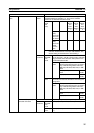
By Config-
urator
Set the areas for the OUT 1/2 and IN 1/2 blocks, the
first words, and the allocation sizes for all slaves
using the Configurator. Blocks can be set for nodes
in any order.
Allocated
words
The input and output areas can be the
following sizes starting from any word in
any of the following areas: CIO Area,
WR Area, HR Area, DM, Area, or EM
Area.
Output
(OUT)
area
500 words max. × 2 blocks
Input (IN)
area
500 words max. × 2 blocks
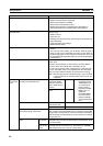
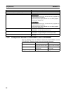
Item Specifications