


48
Nomenclature and Functions Section 2-1
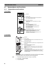
2-1-3 Seven-Segment Display
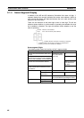
In addition to the MS and NS indicators, DeviceNet Units have a 2-digit, 7-
segment display that normally indicates the master node address. When an
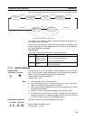
error occurs, the display will alternate between the error code and the node
address of the faulty slave.
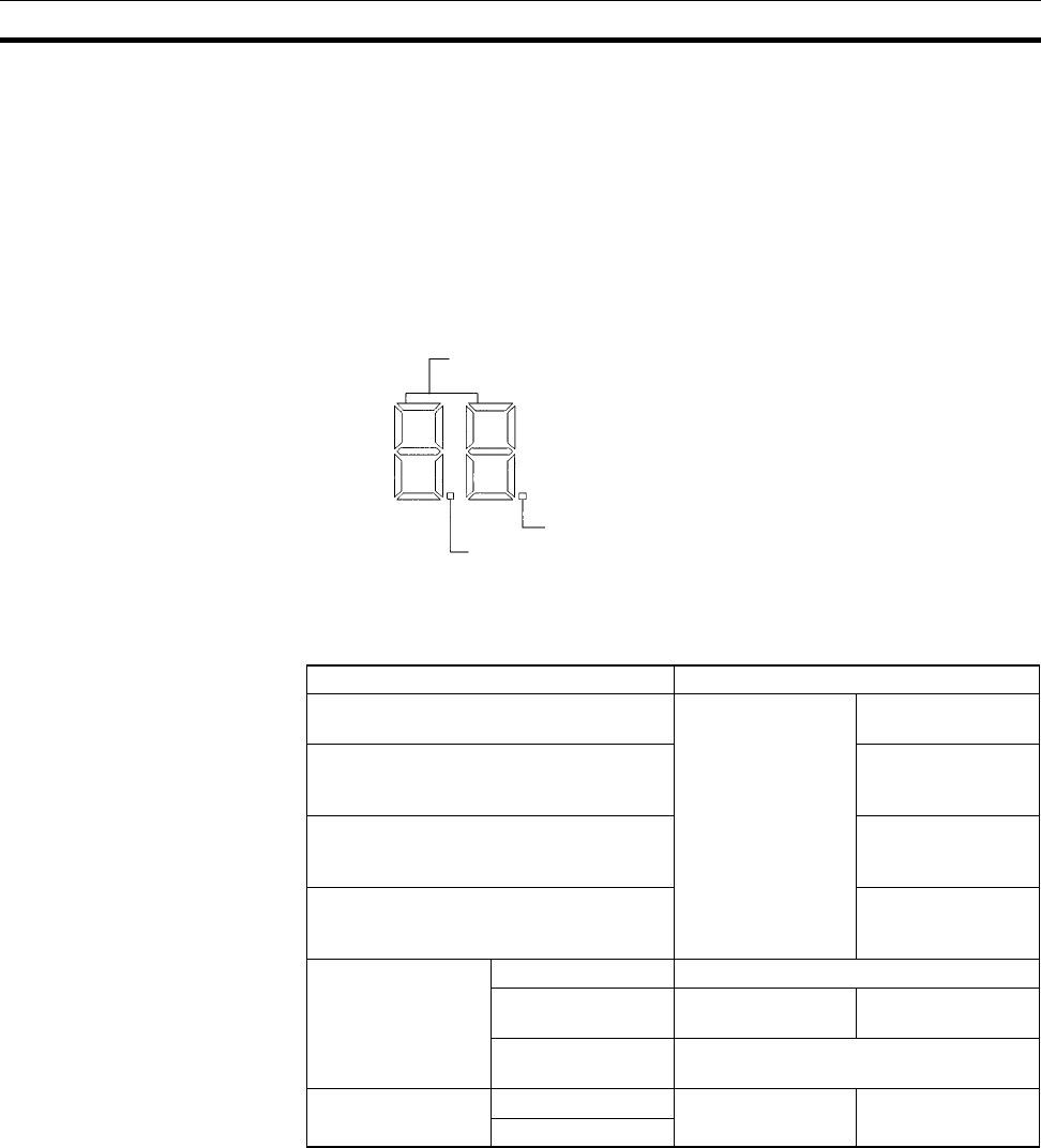
There are dot indicators at the lower-right corner of each digit. The left dot
indicator shows whether or not the master is operating and whether the scan
list is enabled or disabled. The right dot indicator shows whether or not the
slave is operating.
Seven-segment Digits
The following table shows the functions of the 7-segment digits.
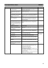
Status Display
Remote I/O communications active and
normal
Displays the mas-
ter’s node address
(00 to 63)
Lit
From power ON to completion of node
address check (master function disabled,
slave function disabled, or both disabled)
Flashing
Remote I/O communications started Flashing (until com-
munications actu-
ally start)
From completion of the node address
check until the start of remote I/O com-
munications
Flashing
Error Watchdog timer Not lit
Memory error or
system error
Error code only Lit
Other errors Alternately displays the error code and
error node address (see diagram below)
Scan list Reading “--” Flashing
Registered
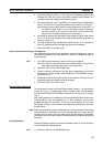
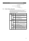
Normal: Master's node address
Error: Error code and faulty node address
Indicates whether the slave is operating or stopped.
Indicates whether the master is operating or stopped and
whether the scan list is enabled or disabled.