


112
User-set Allocations Section 4-4
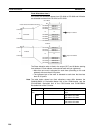
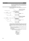
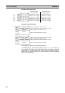
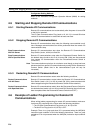
Allocation Size Setup Table
Resulting Slave Allocations
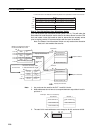
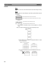
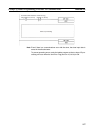
Turning ON the Master User Allocations Switch
Turn ON the Master User Allocations Switch (word n, bit 11, CIO 150011 in
this example). The Master User Allocations Switch will read the allocation
results data for the above slaves and create a scan list based on data for
slaves that are actually online prior to starting remote I/O communications
with the scan list enabled.
Address 0 OUT: 2 (bytes)
Address 1 OUT: 1 (bytes)
Address 2 OUT: 2 (bytes)
Address 3 OUT: 0 (bytes)
Address 4 OUT: 0 (bytes)
Address 5 OUT: 20 (bytes)
OUT sizes specified
in the leftmost byte
Address 0 IN: 0 (bytes)
Address 1 IN: 1 (bytes)
Address 2 IN: 2 (bytes)
Address 3 IN: 1 (bytes)
Address 4 IN: 0 (bytes)
Address 5 IN: 20 (bytes)
IN sizes specified in
the rightmost byte
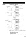
OUT area 1
IN area 1
Address 0
Not used Address 1
Address 2
Address 5
Not used
Address 2
Not used
Address 1
Address 5
Address 0 allocated two bytes (1 word).
Address 1 allocated 1 byte, leftmost byte is not used.
Address 2 allocated two bytes (1 word).
Address 5 allocated 20 bytes (10 words).
Address 1 allocated 1 byte, leftmost byte is not used.
Address 2 allocated two bytes (1 word).
Address 3 allocated 1 byte, leftmost byte is not used.
Address 5 allocated 20 bytes (10 words).
Address 3