


85
Allocated DM Area Words Section 3-3
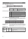
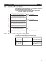
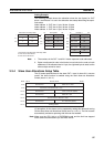
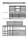
Setting Example
The following example shows the allocation when the size (bytes) for OUT
block 1 and IN block 1 is set in the allocation size setup table using the speci-
fied values.
Node address 0: OUT size: 1 byte, IN size: 5 bytes
Node address 1: OUT size: 4 byte, IN size: 3 bytes
Node address 2: OUT size: 1 byte, IN size: 2 bytes
Note 1. The numbers in the OUT 1 and IN 1 blocks represent node addresses.
2. Bytes are allocated in order in the blocks in word units in the order of node
addresses. If the allocated size is 1 byte, the rightmost byte is used, but the
leftmost byte cannot be used.
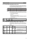
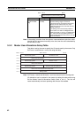
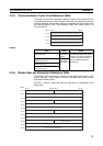
3-3-4 Slave User Allocations Setup Table
The I/O areas specified here for the slave OUT 1 area, for slave IN 1 area are
used if the slave function is enabled using the Slave User-set Allocations
Switch (word n+1, bit 11).
I/O allocations for the slaves can be updated by setting this table and turning
ON the Slave User-set Allocations Switch (word n+1, bit 11). The Unit restarts
automatically and starts operating with the scan list enabled.
Note Make sure the CPU Unit is in PROGRAM mode and the Unit has stopped
slave communications before you set these values.
Allocation size setup table
1 5
4 3
1 2
: :
I
I+1
I+2
OUT block 1
Not usable 00
01 01
01 01
02
s
s+1
s+2
s+3
15 00
Not usable
::
IN block 1
Not usable
00
00 00
01
00
01
k
k+1
k+2
k+3
15 00
::
00
Not usable 01
02 02
k+4
k+5
l: First word of the allocation size setup table
s: First word of OUT block 1
k: First word of IN block 1
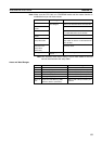
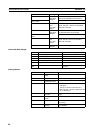
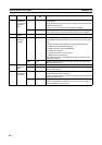
Word
Bit 15 Bit 08 Bit 07 Bit 00
00 Hex fixed
Slave OUT 1 area
m+8
First word of the Slave OUT 1 area
m+9
00 Hex fixed
OUT 1 area size (bytes)
m+10
m+11
First word of the Slave IN 1 area
m+12
m+13
m+14
00 Hex fixed
Slave IN 1 area
00 Hex fixed
IN 1 area size (bytes)
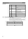
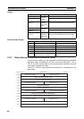
Setting results