


33
Outline of the Configurator Section 1-5
1-5 Outline of the Configurator
Allocations for remote I/O communications can be set in any order of node
addresses from the Configurator. Users can also set remote I/O communica-
tions connections.
Device (master/slave) registration, I/O allocations, and other operations are
especially easy to perform because of graphic operations, including dragging
and dropping icons.
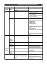
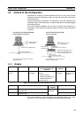
Any of the following methods can be used to connect the Configurator to
DeviceNet. All the connection methods support the same online connection
functions.
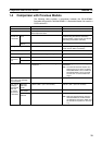
1-5-1 Models
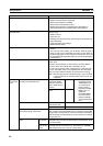
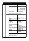
Note Use the following dedicated Boards and Card.
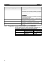
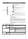
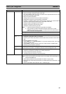
The main functions of the Configurator are illustrated below. For further
details, refer to the DeviceNet Configurator Operation Manual (W382).
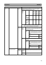
Product Model Contents Method of connecting
personal computer to
network
Personal
computer
OS
Configurator
(Ver. 2.
)
WS02-CFDC1-E Installation disk
(CD-ROM)
Either one of the following
methods
• Serial connection
• Dedicated PCMCIA Card
• Dedicated ISA Board
(see table below)
IBM PC/AT or
compatible
Windows 95,
98, Me, NT4.0
or 2000
Model Contents Personal
computer
OS
3G8F5-DRM21 Dedicated ISA Board and Configurator (Ver.2)
installation disk
IBM PC/AT or
compatible
Windows 95, 98 or NT4.0
3G8E2-DRM21 Dedicated PCMCIA Card and Configurator (Ver.2)
installation disk
Windows 95 or 98
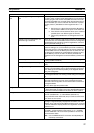
Connection from Dedicated Board/
Card Installed in Computer
Serial Connection from COM
port of Computer
WS02-CFDC1-E
Configurator
ISA Board or PCMCIA Card
DeviceNet Network
DeviceNet network
CS/CJ-series
DeviceNet Unit
Peripheral bus or Host Link
COM port
Peripheral or RS-232C port of
CPU Unit or RS-232C port of
Communications Board/Unit
WS02-CFDC1-E
Configurator
The Configurator is treated as a single
DeviceNet node.
The Configurator is not treated as a
single DeviceNet Node.