


123
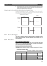
Slave Remote I/O Communications Section 5-1
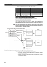
5-1-2 Remote I/O and Slave Communications Specifications
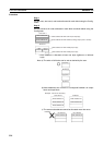
5-1-3 Procedures for Using Remote I/O Slave Communications
Fixed Allocations for Remote I/O
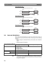
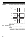
1,2,3... 1. Turn ON the communications, slave, and PC power supplies.
Note Turn ON the communications power supply prior to turning ON the
slave power supply or the slaves may not go online.
2. Switch the CPU Unit to PROGRAM mode.
3. Turn ON the Slave Stop Switch (word n+1, bit 07) from the PC Program-
ming Device to stop slave communications.
4. Turn ON one of the Slave Fixed Allocation Setting Switches (1 to 3: word
n+1, bits 08 to 10) from a Programming Device.
5. Turn ON the Slave Enable Switch (word n+1, bit 06) from a Programming
Device to enable slave communications.
6. Switch the CPU Unit to RUN mode.
Slave remote I/O communications will start up.
Note Slave communications must be disabled prior to area allocation and must be
enabled after area allocation. The order of the procedure is 1) stop slave com-
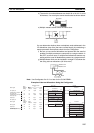
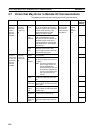
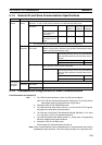
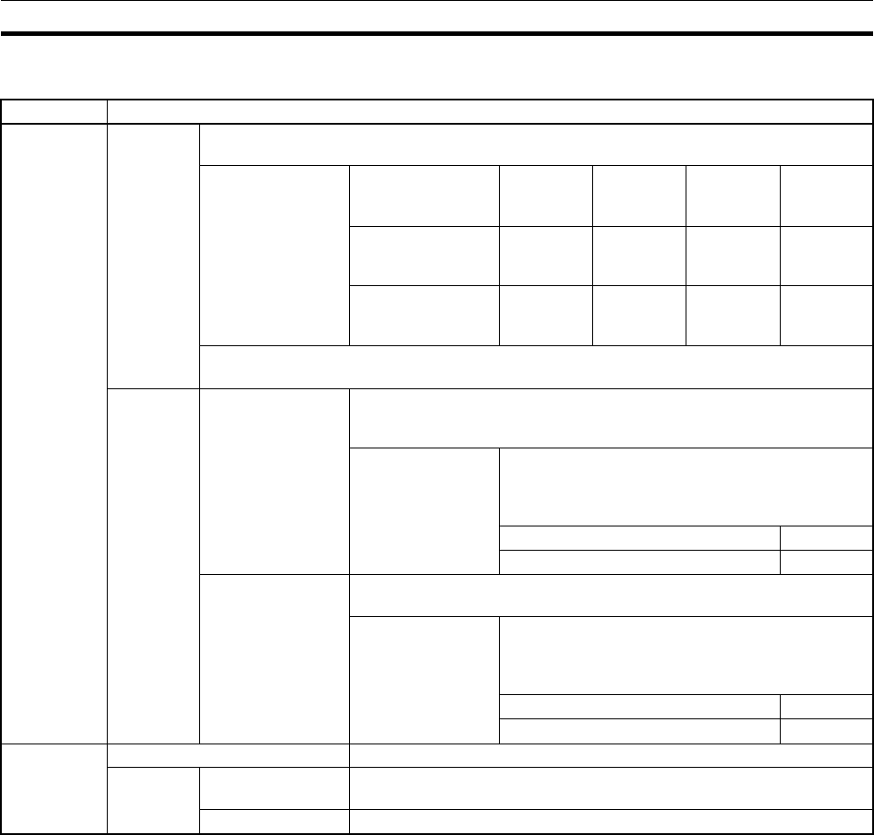
Item Specifications
Allocation
method
Fixed allo-
cations
Select one of the following fixed allocation areas using the Slave Fixed Allocated Area
Switches 1, 2, and 3 in the software switches in the allocated CIO Area words.
Allocated words
(CIO Area)
I/O Size Fixed Allo-
cation Area
Setting 1
Fixed Allo-
cation Area
Setting 2
Fixed Allo-
cation Area
Setting 3
Output (OUT) area
to the slave from
the master
1 word 3370 3570 3770
Input (OUT) area to
the master from the
slave
1 word 3270 3470 3670
Note Select one of the preceding areas using the software switches. All are fixed at 1 word
per node address. The default setting is Fixed Allocation Area Setting 1.
User-set
allocations
By allocated DM
Area words
Set the areas, the first words, and slave allocation size for the OUT 1
and IN 1 blocks (total of 2 blocks) using the Slave User Allocation Setup
Table in the allocated DM Area words.
Allocated words The input and output areas can be the following
sizes starting from any word in any of the following
areas: CIO Area, WR Area, HR Area, DM, Area, or
EM Area.
Output (OUT) area from this slave 100 words
Input (IN) area to this slave 100 words
By Configurator Set the areas for the OUT 1 and IN 1/2 blocks, the first words, and the
slave allocation sizes using the Configurator.
Allocated words The input and output areas can be the following
sizes starting from any word in any of the following
areas: CIO Area, WR Area, HR Area, DM, Area, or
EM Area.
Output (OUT) area from this slave 100 words
Input (IN) area to this slave 100 words
Max. No. of I/
O points per
DeviceNet
Unit slave
Fixed allocations 32 points (1 input word, 1 output word)
User-set
allocations
By allocated DM
Area words
3,200 pts (100 input words, 100 output words)
By Configurator 4,800 pts (100 input words x 2, 100 output words x 1)