


131
User-set Allocations Section 5-3
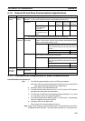
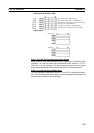
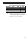
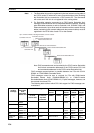
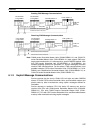
Connection Types and Allocated I/O Areas
The following table shows the relationship between various connection combi-
nations and the allocated areas that are applicable with those connections.
Note 1. With poll + COS connections, the OUT data is the same for poll and COS.
Set the same OUT areas for poll and COS connections when specifying
the areas with the Configurator. With poll + cyclic connections as well, the
OUT data is the same for poll and cyclic. Set the same OUT areas for poll
and cyclic when specifying the areas with the Configurator.
2. Use Configurator Ver. 2.10 or later for the CJ1W-DRM21.
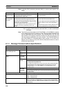
Specified connection
type
OUT 1 area IN 1 area IN 2 area
Poll Poll OUT data Poll IN data Not used
Bit-strobe Not used Bit-strobe IN data Not used
COS COS OUT data COS IN data Not used
Cyclic Cyclic OUT data Cyclic IN data Not used
Poll+bit-strobe Poll OUT data Poll IN data Bit-strobe IN data
Poll+COS (See note.) Poll/COS OUT data Poll IN data COS IN data
Poll+cyclic (See note.) Poll/cyclic OUT data Poll IN data Cyclic IN data
COS+bit-strobe COS OUT data COS IN data Bit-strobe IN data
Cyclic+bit-strobe Cyclic OUT data Cyclic IN data Bit-strobe IN data