


127
User-set Allocations Section 5-3
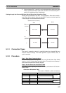
2. Only two blocks (OUT 1 and IN 1) can be allocated when setting are made
with the allocated DM Area words area, but there are three blocks (OUT 1
and IN 1/2) available with the Configurator.
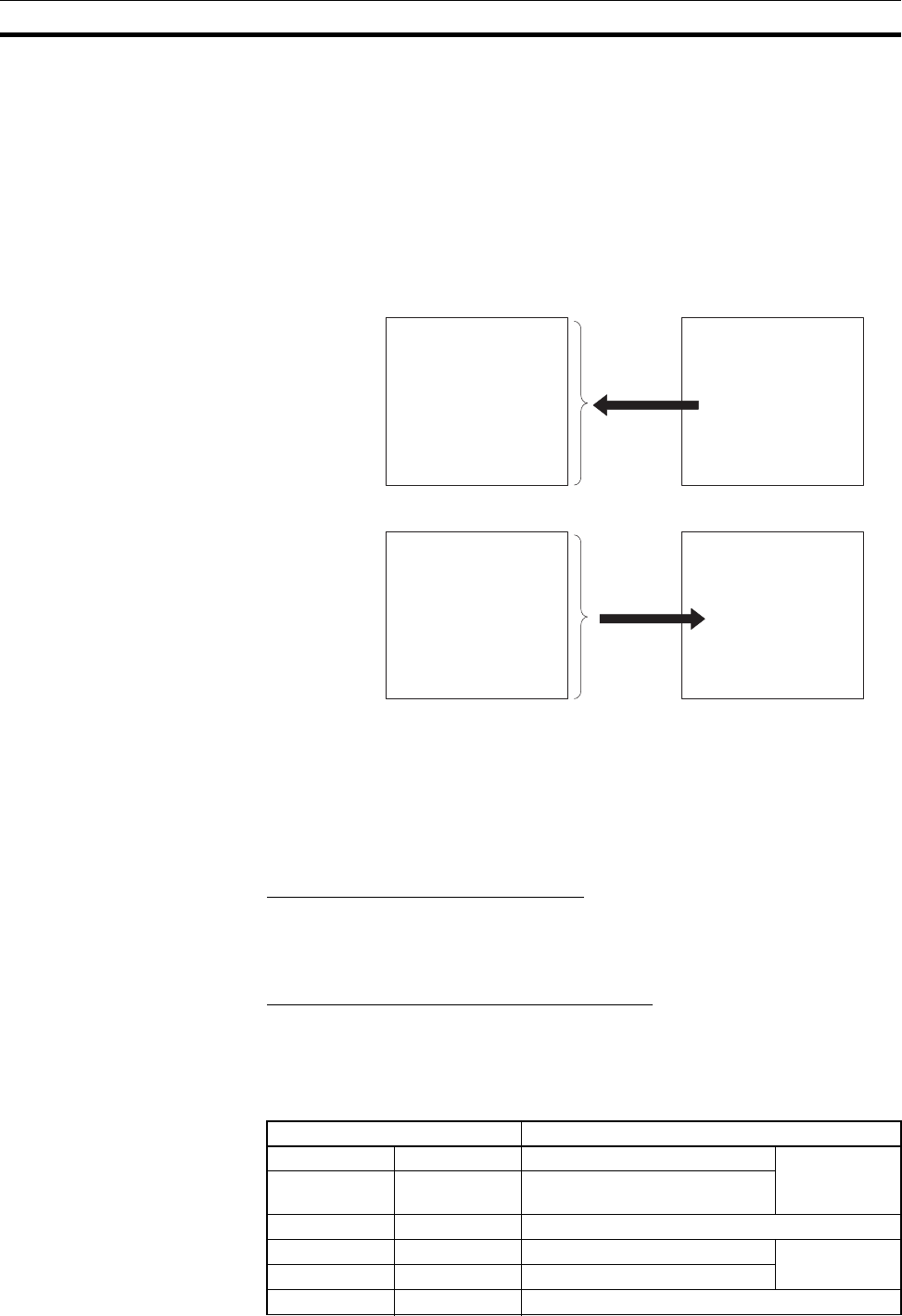
Setting through the Allocated DM Area Words (Slave User Allocations Table)
Words can be allocated for the OUT 1 area (master to Slave Unit) and IN 1
area (Slave Unit to master) from any specified I/O memory location specified
in the settings in the allocated DM area words.
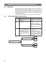
5-3-1 Connection Types
The type of connection cannot be specified when the allocated DM area
words is used for settings. The master specifies a poll, bit-strobe, COS, or
cyclic connection.
5-3-2 Procedure
Step 1: Stop Slave Communications
If the Unit is already functioning as a slave, turn ON the Slave Stop Switch
(word n+1, bit 07) to stop slave communications. This step is not necessary if
slave communications have already stopped.
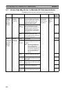
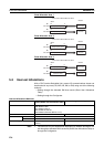
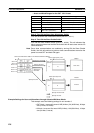
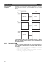
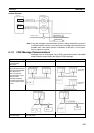
Step 2: Set the Slave User Allocations Table
This table is used to specify the areas, first words, and sizes for OUT block 1
and IN block 1.
• Slave User Allocations Table
First word m = D30000 + (100 x unit number)
Specified area in I/O memory
Slave
Bit
First word
specified
OUT 1 area OUT area
Master
IN area
IN 1 area
15 0
to
Bit
First word
specified
15 0
to
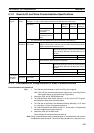
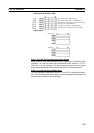
Allocated DM area words Details
Word m+8 Bits 00 to 07 Slave OUT 1 area Select from fol-
lowing table
Word m+9 Bits 00 to 15 First word of the slave OUT 1
area
Word m+10 Bits 00 to 07 Slave OUT 1 area size (in bytes)
Word m+11 Bits 00 to 07 Slave IN 1 area Select from fol-
lowing table
Word m+12 Bits 00 to 15 First word of the slave IN 1 area
Word m+13 Bits 00 to 07 Slave IN 1 area size (in byte)