


109
User-set Allocations Section 4-4
Procedure Step 1: Turn ON the Master Enable Switch
Make sure that master communications have disabled by checking to see if
Master Enable Function Flag (word n+11, bit 03) is OFF and then turn ON the
Master Enable Switch (word n+14, bit 06) to enable master communications.
Once master communications have been enabled by turning this switch ON,
they will remain enabled even if the power is turned OFF and back ON again.
Note Do not turn ON the Master Enable Switch unless master communi-
cations are stopped. (If the Master Enable Switch is turned ON when
master communications are enabled, a Unit error will occur and a C5
error will be displayed on the 7-segment display on the front panel.)
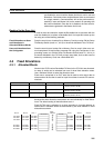
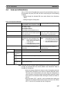
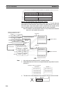
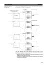
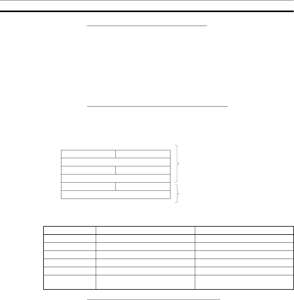
Step 2: Setting the Master User Allocations Table
This table specifies the area and first word for each block and the area and
first word for the Allocation Size Setup Table.
• Master User Allocations Table
• Areas and Word Ranges for OUT Block 1, IN Block 1, and the Alloca-
tion Size Setup Table
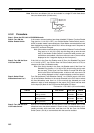
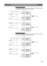
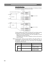
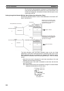
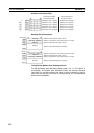
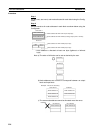
Step 3: Setting the Allocation Size Setup Table
Specify the area and first word in this table at words m+5 and m+6. IN and
OUT sizes for all nodes are set here as shown in the table below. The setting
range for each node is 0 to 200 bytes (0 to 100 words), although actual size
depends on the allocated slaves. The maximum size per block is 500 words. If
the size set here is larger than 1 byte, the start bit for all slaves is bit 00 and
size is allocated in ascending node address order starting from the beginning
of the OUT 1 and IN 1 areas in word units. If the size is set at 0 bytes for a
node address, it is skipped the words are allocated to the next address.
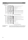
• Allocation Size Setup Table
First word m = D30,000+(100 x unit no.)
Bit
OUT block 1 area
First word of OUT block 1
IN block 1 area
First word of IN block 1
Area for Allocation
Size Setup Table
First word of Allocation Size Setup Table
Can be set anywhere past here.
Can be set anywhere past here.
15 08 07 00
m+1 wd
m+2 wd
m+3 wd
m+4 wd
m+5 wd
m+6 wd
00
00
00
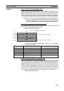
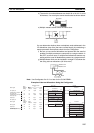
Code Name Word range
00 Hex --- The block is not used.
01 Hex CIO Area (CIO) 0000 to 17FF Hex (0 to 6143)
03 Hex Data Memory (DM) 0000 to 7FFF Hex (0 to 32767)
04 Hex Work (WR) 0000 to 01FF Hex (0 to 511)
05 Hex HR (HR) 0000 to 01FF Hex (0 to 511)
08 to 14 Hex Expansion Data Memory (EM)
Bank 0 to bank C (13 banks)
0000 to 7FFF Hex (0 to 32767) for all
banks