


27
Specifications Section 1-3
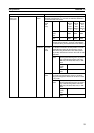
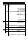
Other func-
tions
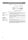
Remote programming/monitoring func-
tions
A CX-Programmer connected to the serial communications port
of a PC to which a CS/CJ-series DeviceNet Unit is mounted can
remotely program and monitor DeviceNet slave PCs with a CS/
CJ-series DeviceNet Unit mounted. Either the peripheral port or
built-in RS-232C port can be used with the Host Link or periph-
eral bus protocol. (Scheduled for CX-Programmer Ver. 2.1 or
later)
Note 1. Serial ports on a Serial Communications Board/Unit
can be used in addition to the ports on the CPU Unit.
2. Inter-network communications across up to 3 levels is
possible (even over different types of network).
3. This is also possible from a CX-Programmer on net-
work.
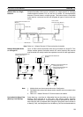
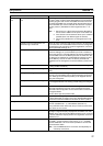
Operation from the Configurator con-
nected through a serial line
Allows all online monitoring and setup functions to be performed
on a master PC on the DeviceNet network from the Configurator
connected through a serial line (scan list registration, communi-
cations parameter settings, etc.).
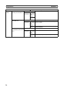
Memory Card backup function Allows DeviceNet Unit data settings (scan list, communication
cycle time settings, etc.) to be backed up as a file to a Memory
Card in the CPU Unit. The data settings can also be restored into
the DeviceNet Unit from the Memory Card in the CPU Unit. Set-
ting data can be restored into a DeviceNet Unit simply by carry-
ing the Memory Card to the site if the device parameter file
prepared from the Configurator is saved to Memory Card from a
PC.
Error history in the DeviceNet Unit Supported. (The history can be accessed up by the Configurator
or using a FINS command.)
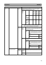
Communications cycle time setting Supported (in the allocated DM Area words or from the Configu-
rator).
Message monitoring timer Sets the response monitoring time (explicit connection opening
interval) in the DeviceNet Unit for explicit message communica-
tions. Settings can be made separately for all targeted devices
using the Configurator.
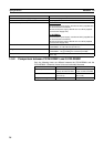
COS/cyclic heartbeat timer setting Sets the minimum SEND interval in COS or cyclic connections
for all targeted devices. The setting is made using the Configura-
tor.
Device data check function Performs a comparison check on the following device data when
slave data registered in the scan list is compared with actual
slave data. The Configurator can be used to set this function for
all targeted Slaves.
Vendor, device type and product code
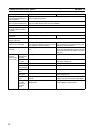
Configurator connection method 1) Serial connection (peripheral bus or Host Link)
2) Direct DeviceNet connection through a dedicated Board/Card
The online functions available are the same for both 1) and 2).
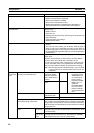
Setting section Rotary switches:
Unit No. (hexadecimal x 1), node address (decimal x 2)
Front panel DIP switch: Baud rate, stop or continue communica-
tions when an error occurs
Display section Two LED indicators (2 colors): Display Unit and network status.
Two-digit 7-segment display: Displays the DeviceNet Unit node
address, error code, and node address where an error occurred.
2 dot LED indicators: Display whether the registration scan list is
enabled or not.
Front connector One communications connector (communications data: CAN H
and CAN L, communications power supply: V+, V–, shielded)
Use the XW4B-05C1-H1-D connector provided to connect the
communications cable.
Note Use the XW4B-05C4-T-D connector sold separately for
multi-drop connections.
Item Specifications