


130
User-set Allocations Section 5-3
Setting through the
Configuration
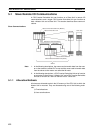
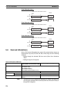
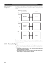
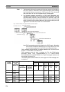
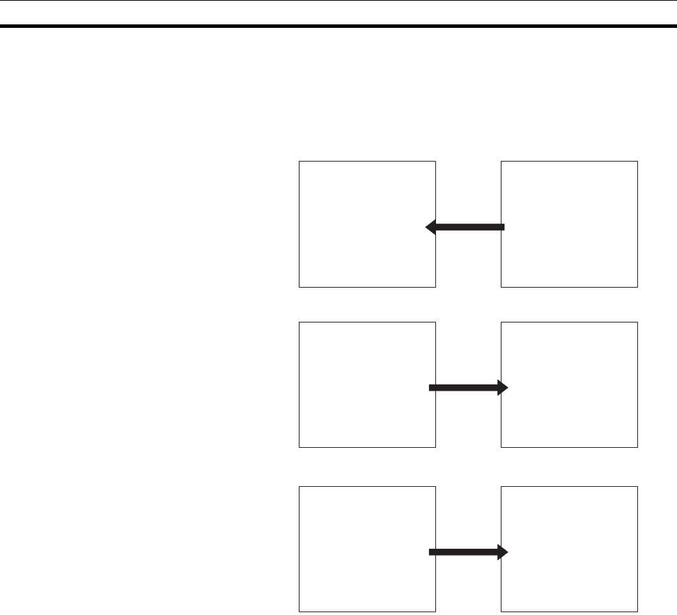
A maximum of three blocks can be allocated at any locations in I/O memory
for the output (OUT) area block 1, input (IN) area block 1, and input (IN) area
block 2.
The block allocation order and block allocation areas can be set as required.
Refer to the DeviceNet Configurator Operation Manual (W382) for details on
the allocation procedure.
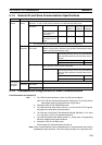
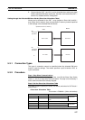
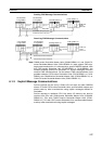
5-3-3 Connection Types
The type of connection can be specified if the Configurator is used for set-
tings. The number of applicable allocation areas varies with the type of con-
nection used.
• A maximum of three areas (OUT 1, IN 1, and IN 2) can be used when
multiple connections are specified.
• Two allocation areas (OUT 1 and IN 1) can be used if the automatic con-
nection setting or a single connection is specified.
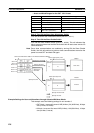
Specified area in I/O memory
User-set block order
Master
Slave output
(OUT) area 1
OUT area
Slave input
(IN) area 1
IN area
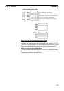
Bit
First word
specified
15 0
to
Bit
First word
specified
15 0
to
Slave input
(IN) area 2
IN area
Bit
First word
specified
15 0
to