


101
Fixed Allocations Section 4-3
you disable the scan list with a Master Unit that is set for user-set
allocations. Particularly when multiple Master Units are connected
to a single network, communications will not be performed suc-
cessfully if even one Master Unit on the network is operating with
the scan list disabled. Once the list is disabled, the user-set allo-
cations data registered in the Master Unit is lost.
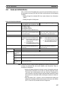
Backing Up the Scan List
A scan list must be created to switch the DeviceNet Unit to operation with the
scan list disabled or to replace a DeviceNet Unit. It is important to back up the
list using one of the following methods:
Fixed Allocations or User-
set Allocations in
Allocated DM Area Words
Save the scan list as a backup file on Memory Card by turning ON the Setup
File Backup Switch (word n+1, bit 15) in the words allocated in the CIO Area.
User-set Allocations from
the Configurator
Save the scan list as a backup file on Memory Card or save it either as a net-
work component file and master parameter file using the Configurator. In the
preceding cases, turn ON the Setup File Restore Switch (word n+1, bit 14) in
the words allocated in the CIO Area to input setup data, such as the scan list
backed up on Memory Card, into a DeviceNet Unit.
4-3 Fixed Allocations
4-3-1 Allocated Words
Words in the CS/CJ-series DeviceNet CIO Area in the CPU Unit are allocated.
An area of words can be selected from one of three fixed allocation areas.
Use a Software Switch to select the allocation area.
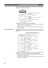
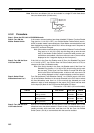
Each area is comprised of an OUT area that is used to write output data to
slaves and an IN area that is used for input from slaves in remote I/O commu-
nications.
A maximum of 3 DeviceNet Units can be included as masters in a single PC
because the three allocation areas above are set individually for fixed alloca-
tions. The default setting is fixed allocations area 1.
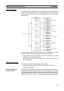
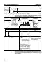
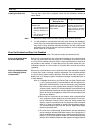
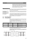
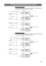
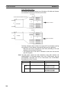
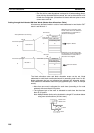
Each OUT/IN area is allocated to a slave according to its node address as
shown below. Allocated words are determined by the node address in fixed
allocations as shown.
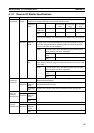
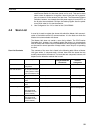
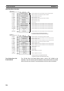
Area OUT area (word) IN area (word) Selection method
Fixed allocation area 1 CIO 3200 to CIO 3263 CIO 3300 to CIO 3363 Turn ON the Master Fixed Allocation Setting
1 Switch (word n, bit 08).
Fixed allocation area 2 CIO 3400 to CIO 3463 CIO 3500 to CIO 3563 Turn ON the Master Fixed Allocation Setting
2 Switch (word n, bit 09).
Fixed allocation area 3 CIO 3600 to CIO 3663 CIO 3700 to CIO 3763 Turn ON the Master Fixed Allocation Setting
3 Switch (word n, bit 10).
Area 3 Area 2 Area 1
OUT area
Node
address
IN area
Area 1 Area 2 Area 3
CIO 3600 CIO 3400 CIO 3200 CIO 3300 CIO 3500 CIO 3700
CIO 3601 CIO 3401 CIO 3201 CIO 3301 CIO 3501 CIO 3701
CIO 3602 CIO 3402 CIO 3202 CIO 3302 CIO 3502 CIO 3702
CIO 3661 CIO 3461 CIO 3261 CIO 3361 CIO 3561 CIO 3761
CIO 3662 CIO 3462 CIO 3262 CIO 3362 CIO 3562 CIO 3762
CIO 3663 CIO 3463 CIO 3263 CIO 3363 CIO 3563 CIO 3763