


125
Fixed Allocations Section 5-2
Note 1. Enable slave communications in CS1W-DRM21 or CJ1W-DRM21 proper-
ties if the Configurator is used.
2. Use Configurator Ver. 2.10 or later for the CJ1W-DRM21.
5-2 Fixed Allocations
5-2-1 Allocated Words
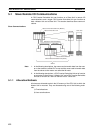
Words in the CS/CJ-series DeviceNet CIO Area in the CPU Unit are allocated.
Words can be selected from one of three fixed allocation areas. Use a Soft-
ware Switch to select the allocation area.
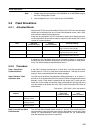
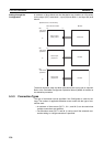
Each area is comprised of an OUT area that is used to write data to the mas-
ter IN area and an IN area that is used for inputs from the master OUT area in
remote I/O communications.
A maximum of 3 DeviceNet Units can be included as slaves in a single PC
because the three allocation areas above are set individually for fixed alloca-
tions. The default setting is fixed allocations area 1.
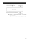
5-2-2 Procedure
Step 1: Stop Slave
Communications
If the Unit is already functioning as a Slave Unit, turn ON the Slave Stop
Switch (word n+1, bit 07) to stop slave communications. This step is not nec-
essary if slave communications have already stopped.
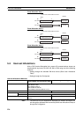
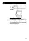
Step 2: Select a Fixed
Allocation Area
Turn ON one of the Slave Fixed Allocation Setting Switches (1 to 3: word n+1,
bits 08 to 10) in the allocated CIO Area words to select a fixed allocation area
between 1 and 3. One words is allocated for the output (OUT) area from the
Slave Unit to the master and another word is allocated for the input (IN) area
from the master to the Slave Unit in the CS/CJ-series DeviceNet CIO Area, as
shown below.
First word n = CIO 1500 + (25 x unit number)
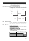
Step 3: Turn ON the Slave
Enable Switch
Turn ON the Slave Enable Switch (word n+1, bit 06). This will allocated the
fixed allocation areas as slave areas and the DeviceNet Unit will start slave
remote I/O communications. Slave communications will run automatically
after that whenever the power is turned ON.
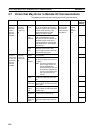
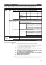
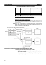
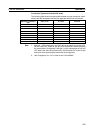
Area OUT area
(master to slave)
IN area
(slave to master)
Selection method
Fixed allocation area 1 CIO 3370 CIO 3270 Turn ON the Slave Fixed Allocation Set-
ting 1 Switch (word n, bit 08).
Fixed allocation area 2 CIO 3570 CIO 3470 Turn ON the Slave Fixed Allocation Set-
ting 2 Switch (word n, bit 09).
Fixed allocation area 3 CIO 3770 CIO 3670 Turn ON the Slave Fixed Allocation Set-
ting 3 Switch (word n, bit 010).
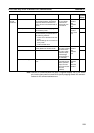
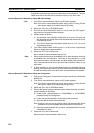
Software switch
address
Software switch name Fixed allocation area Allocated output
(OUT) area
(master to slave)
Allocated input (IN)
area
(slave to master)
Word n+1, bit 08 Slave Fixed Allocation
Setting 1 Switch
Fixed allocation area 1 CIO 3370 CIO 3270
Word n+1, bit 09 Slave Fixed Allocation
Setting 2 Switch
Fixed allocation area 2 CIO 3570 CIO 3470
Word n+1, bit 10 Slave Fixed Allocation
Setting 3 Switch
Fixed allocation area 3 CIO 3770 CIO 3670