


51
Installing the DeviceNet Unit Section 2-2
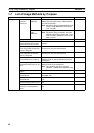
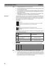
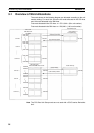
Continue/Stop Remote I/O Communications
When the DeviceNet Unit is used as a master, pin 3 is used to set whether or
not communications will stop after a communications error.
If pin 3 is ON, remote I/O communications will be stopped if one of the follow-
ing errors occurs.
Remote I/O Communications Error Flag (n+12, bit 02 is ON)
Send Timeout Flag (n+10, bit 08 is ON)
Network Power Error Flag (n+10, bit 07 is ON)
Remote I/O communications will remain stopped even if the error is cleared.
(Message communications and slave functions will continue.) To resume com-
munications, turn ON the Remote I/O Communications Start Bit (word n, bit
02) of Software Switches 1. Refer to 3-2 Allocated CIO Area Words for details.
Note The 7-segment display will show “A0” when remote I/O communications stop.
Refer to SECTION 9 Troubleshooting and Maintenance.
If pin 3 is OFF, remote I/O communications will stop if a send timeout or net-
work power error occurs, but will restart automatically when the cause of the
error is cleared.
Hold/Clear Remote Outputs
When the DeviceNet Unit is used as a slave, pin 4 is used to set whether to
hold or clear remote outputs when a communications error occurs.
Note If the DeviceNet Unit is used as a slave, the 7-segment display will show “L9”
when remote I/O communications stop. Refer to SECTION 9 Troubleshooting
and Maintenance.
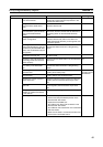
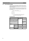
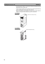
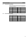
Communications
Connectors
Color stickers that match communications cable colors are attached to the
communications connectors. Match the colors when connecting communica-
tions cables to the connectors. These colors are given in the following table
For details on communications specifications and wiring, refer to DeviceNet
(CompoBus/D) Operation Manual (W267).
Note Before connecting communications cables, turn OFF the PC power supply, all
slave power supplies, and the communications power supply.
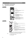
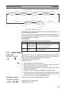
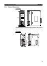
2-2 Installing the DeviceNet Unit
2-2-1 System Configuration Precautions
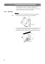
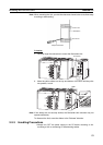
• I/O words are allocated to CPU Bus Units according to the unit number
setting on the switch located on the front panel of the Unit, not according
to Unit slot numbers. Refer to 3-1 Overview of Word Allocations.
Pin 3 Function
OFF Continue communications.
ON Stop communications.
Color Signal
Black Power line, negative voltage (V–)
Blue Communications line, low (CAN L)
--- Shield
White Communications line, high (CAN H)
Red Power line, positive voltage (V+)