


194
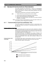
Remote I/O Communications Characteristics Section 8-1
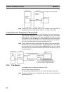
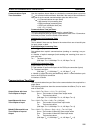
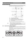
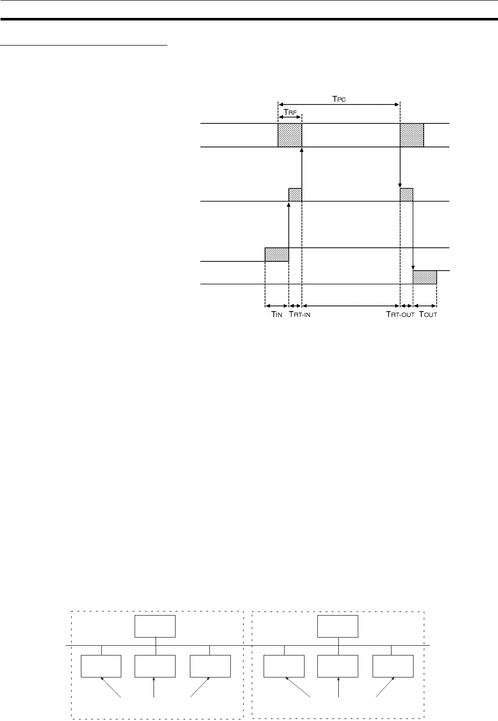
Minimum I/O Response Time
The minimum I/O response time occurs when the Slave’s I/O refreshing is
executed just after the input signal is received by the DeviceNet Unit and the
output signal is output at the beginning of the next I/O refresh cycle.
T
IN
: The Input Slave’s ON (OFF) delay
T
OUT
: The Output Slave’s ON (OFF) delay
T
RT-IN
: Input Slave’s communications time/Slave (See page 191.)
T
RT-OUT
: Output Slave’s communications time/Slave (See page 191.)
T
PC
:The PC’s cycle time
T
RF
:The PC’s DeviceNet Unit refresh time (See page 192.)
The minimum I/O response time (T
MIN
) is the total of the following terms:
T
MIN
= T
IN
+ T
RT-IN
+ T
PC
+ T
RF
+ T
RT-OUT
+ T
OUT
Note 1. Refer to the CompoBus/D (DeviceNet) Slaves Operation Manual (W347)
for details on the Input and Output Slaves’ delay times.
2. Refer to Refresh Time on page 192 and to the PC’s Operation Manual for
details on the PC’s cycle time.
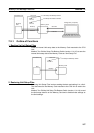
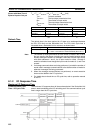
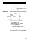
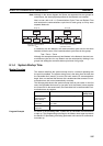
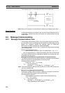
8-1-3 More than One Master in Network
The following equation shows the remote I/O communications cycle time
(T
RM
) when there is more than one master in the network. An example for two
masters is used.
First, the network is divided into two groups: Master A and the slaves in
remote I/O communications with it and master B and the slaves in remote I/O
communications with it.
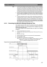
Instruction
execution
PC
Master Unit processing
Output
Input
(TPC+TRF)
Group A
Master A
Slave A
Slave B
Slave C
Slaves in remote I/O commu-
nications with Master A
Group B
Master B
Slave D Slave E
Slave F
Slaves in remote I/O commu-
nications with Master B