


38
Basic Operating Procedures Section 1-6
message communications may not be possible unless the DeviceNet Unit
is registered in the local network table.
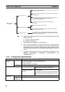
1-6-4 Procedures Prior to Starting Communications
Using the Master Function
To use the master function, the Master Enable Switch (word n, bit 06) must be
turned ON from a Programming Device. Enable master communications
through CS1W-DRM21 properties if you are using a Configurator.
Note 1. Make sure the scan list is enabled when using the master function. This
will allow you to check whether slaves are online or not from the CPU Unit
so that you will be able to determine whether or not the DeviceNet is com-
municating properly.
2. Remote I/O communications with a specified slave can be turned OFF
(disconnected) by turning ON (1) the corresponding Disconnect/Connect
Switch (words n+6 to n+9) when a slave is replaced or is registered in the
scan list prior to being connected. These switches are cleared when the
power supply is turned OFF, however, so a bit must be turned back ON (1)
from the ladder program when the power turns ON for it to be valid again.
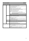
Fixed Allocations
Use the following procedure to use fixed allocations. Refer to 4-3 Fixed Alloca-
tions for details on fixed allocations.
1,2,3... 1. Turn ON the communications, slave, and PC power supplies.
Note Turn ON the communications power supply before turning ON the
slave power supplies or the slaves may not go online.
2. Switch the CPU Unit to PROGRAM mode.
3. Check Unit Status 2 (word n+11, bit 03) from a Programming Device con-
nected to the CPU Unit to see if the master function is ON (enabled). If it
is enabled, skip step 4 below and proceed to step 5.
4. If the master function is OFF (disabled), turn ON the Master Enable Switch
(word n, bit 06) from a Programming Device connected to the CPU Unit.
Note Execute this only when master communications are turned OFF. (If
the Master Enable Switch is turned ON when master communica-
tions are ON, a Unit error will occur and a C2 error will be displayed
on the 7-segment display on the front panel.)
5. Turn ON the Master Fixed Allocation Area Setting 1 to 3 Switches (word n,
bits 8 to 10). Master remote I/O communications will begin with the scan
list disabled.
6. Turn ON the Scan List Enable Switch (word n, bit 00). Master remote I/O
communications will begin with the scan list enabled.
7. Switch the CPU Unit to RUN mode.
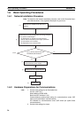
User-set Allocations Using Allocated DM Area Words
Use the following procedure to set allocations using the words allocated to the
Unit in the DM Area. Refer to 4-4 User-set Allocations for details on user-set
allocations.
1,2,3... 1. Turn ON the communications, slave, and PC power supplies.
Note Turn ON the communications power supply before turning ON the
slave power supplies or the slaves may not go online.
2. Switch the CPU Unit to PROGRAM mode.