107
Reference Manual
IP2048/RM, Rev AA
Appendix F: Configuring Using HART
February 2015
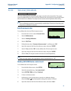
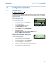
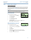
F.3.7 Upper blanking (P023)
This defines a zone close to the transmitter where echoes are to be ignored. Establishing this
zone eliminates echoes from false targets such as mounting fittings or the end of stub pipes.
Enter the vertical distance from the transmitter face to where a valid surface echo can be
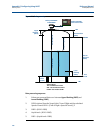
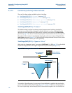
detected. See Figure F-1 on page 106 for this zone in a tank geometry illustration.
Note
To avoid a false high level alarm, the upper blanking distance should not be set to less than
the factory default setting.
The pulse transmission stops if the sum of the Lower Blanking (page 110) and Upper
Blanking and is greater than the Bottom Reference (page 105).
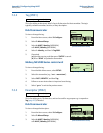
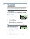
Field Communicator
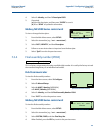
To view or change the upper blanking distance:
1. From the Home screen, select 2: Configure.
2. Select 2: Manual Setup.
3. Select 5: Engineering (MSP900GH)
or 6: Engineering (MSP400RH).
4. Select 5: Upper Blanking P023.
5. If a change is required:
(a) Input the new blanking distance, and press “ENTER” to save it.
(b) Press “SEND” to update the transmitter.
Note
When messages appear, take appropriate action if needed and press “OK”.
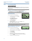
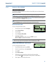
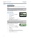
Mobrey MCU900 Series control unit
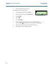
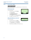
To view or change the upper blanking distance:
1. From the Main Menu screen, select SETUP.
2. Select the transmitter (e.g. “Tx1:MSP400RH”).
3. Select ENGINEERING.
4. Select Upper Blanking.
5. Follow the on-screen instructions to edit and save the new setting.
(Press the Enter ( ) key if prompted to change mode to “off-line”).
6. Select “Quit” to exit to the previous menu.
Fast Keys
2, 2, 5 [or 6], 5
Upper Blanking P023
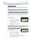
1.000 ft
1.000 ft
ESC
DEL ENTER
HELP
w
s
q
a
z
Lock
Shift
@ &
á ü
x
e
d
c
r
f
v
t
g
b
y
h
n
u
j
m
*
-
+
/
.
0
7
4
1
8
5
2
9
6
3
i
k
o
l
FN
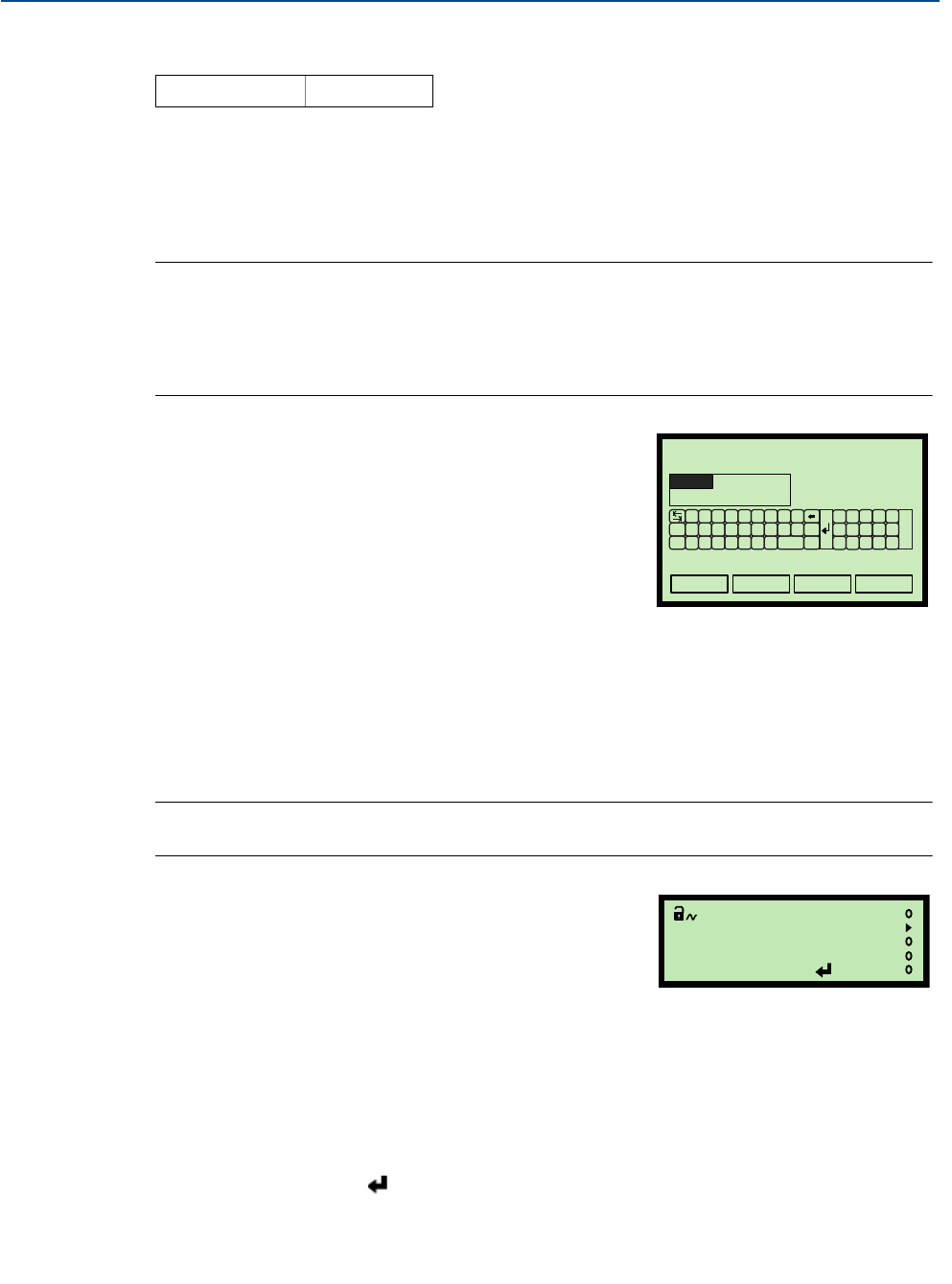
(Field Communicator Screen)
Upper Blanking P023
1.000ft
Esc=Quit =Edit
(Mobrey MCU901 Screen)


