19
Reference Manual
IP2048/RM, Rev AA
Section 3: Installation
February 2015
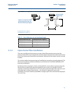
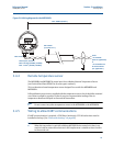
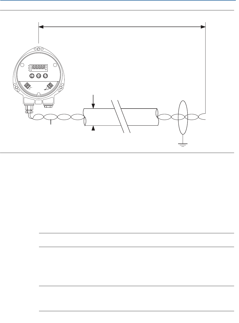
Figure 3-8. Wiring diagram for the MSP900GH
3.4.4 Remote temperature sensor
The MSP400RH and MSP900GH accept input from a Mobrey Remote Temperature Sensor
(see Product Data Sheet IP2045 for accessory part numbers).
This is a thermistor-based temperature sensor designed for use with the MSP400RH and
MSP900GH.
Full installation instructions are supplied with the temperature sensor, but it should be mounted
out of direct sunlight in a position so that it can give a representative reading of the air
temperature between the liquid surface and the transmitter.
Note
Do not connect any other temperature sensor to the MSP400RH or the MSP900GH.
3.4.5 Wiring to allow HART communications
If HART communications is required, a 250 Ohms (minimum), 0.25 W load resistor must be
installed in the loop. (See “Dimension drawings” on page 68).
Note
When the transmitter is used with a Mobrey MCU900 Series control unit, there is no
need to install an external load resistor in the loop because a suitable resistor is built in
to the control unit.
Min. 12 Vdc
Ø4 to 8 mm
(0.15 to 0.31 in.)
Twisted-pair, Screened
Min. 0.22 mm
2
(24 SWG / 23 AWG)
Max. 1.5 mm
2
(16 SWG / 18 AWG)
0 Vdc
Max. 3000 m (9750 ft.)
+12 to 40 Vdc
(Non I.S. Application)
or
+12 to 30 Vdc From
Protective Barrier
(I.S. application.)


